LS swaps are one of the hottest things going in the automotive aftermarket, and that includes shoehorning them into Corvettes that rolled out of St. Louis thirty or forty years before the LS1 debuted in 1997. Powerful, lightweight, and relatively drama-free, the ultra-efficient LS engines make big-block power out of a small-block package and get ridiculously high gas mileage. They have no right to be this good…but they are. Fitting one into an early Corvette is easy; there’s plenty of room in Sharks and Midyears to accommodate the compact package, and engine mount adaptors are readily available to bolt it in place. Wiring can be as easy or complicated as you want to make it, and plumbing the fuel system is relatively straightforward. But adding serious LS package power also means beefing up virtually every other system on the car, including the all-important cooling system.
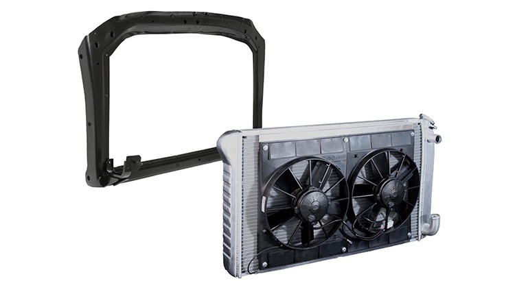
We drove our ’72 coupe to Tray Walden’s Street Shop, Inc. in Athens, Alabama, where we removed the serviceable 300hp smallblock 350 in favor of an LS3 stroker that dynoed at well over 600. Once we had the engine and its new T56 Magnum six-speed transmission in place, we turned to the radiator and the rest of the cooling system. It’s easy to love these cars so much that we forget how old they are, but you’ll quickly remember once you take one apart and find rust. The radiator core support is a classic rust spot due to decades of leaks and overflow. In our case, the support had only surface rust, but still needed to be upgraded to make sure our aluminum DeWitt’s radiator (which was made for LS conversions) would fit.
To hold the DeWitts unit, we ordered a big block radiator core support from Corvette Central. We also required upper mounting brackets (lower ones already come attached to the core support) with rubber cushions, and foam seals to go between radiator and support to make sure all the air flows through the radiator, rather than around it.
Unfortunately, factory hoses wouldn’t fit, so we resorted to bending pieces of metal rod in the basic shape we needed and then adjourned to the local auto parts store, where we wandered through the back room until we found hoses in the general contour and length we needed. Fitting these was relatively simple, as was adding the LS-specific steam line that routes to the radiator.
This wasn’t the end of the work, however. You don’t put 600 hp into a Corvette without intending to use it, and the only legal place to unwind that kind of power is on a racetrack where you are expected to have some sort of “catch can” to keep your radiator from overflowing onto the track. Though we purchased a universal aluminum unit, we couldn’t make it fit into the confines of our engine compartment; we were forced to build our own. Starting with an aluminum bottle, I machined a threaded fitting for the bottom of the can while Tray Walden drew out a lid for it in a CAD program, and then machined it on-site in a CNC mill. Once done, Tray welded up the bottle, adding a mounting bracket. After that we screwed in the hose fitting on the bottom and the breather in the top, and bolted it in place on the inner fender. All that’s left is to send it off to be polished, then bolt it back in place.

This is what we started with: a reliable, inoffensive smallblock coupe powered by a 300-horse 350, augmented by a 100-shot of nitrous oxide.
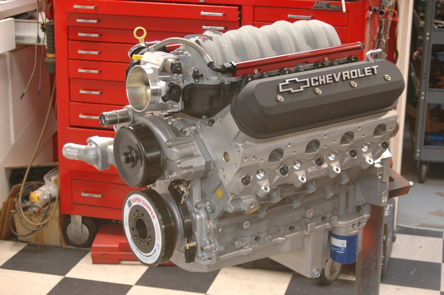
This is what we put in it: a Grimes-built 416ci LS3 using top-shelf parts from Lunati, Wiseco, FAST, RHS, and Comp Cams. It dynoed at 635 hp/543 ft lbs, over twice the output of our old 350.
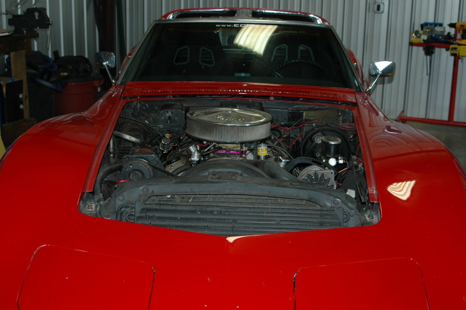
You’ve got to tear it down before you can reassemble it, so the first order of business is to pull the hood and get to work on what’s underneath.
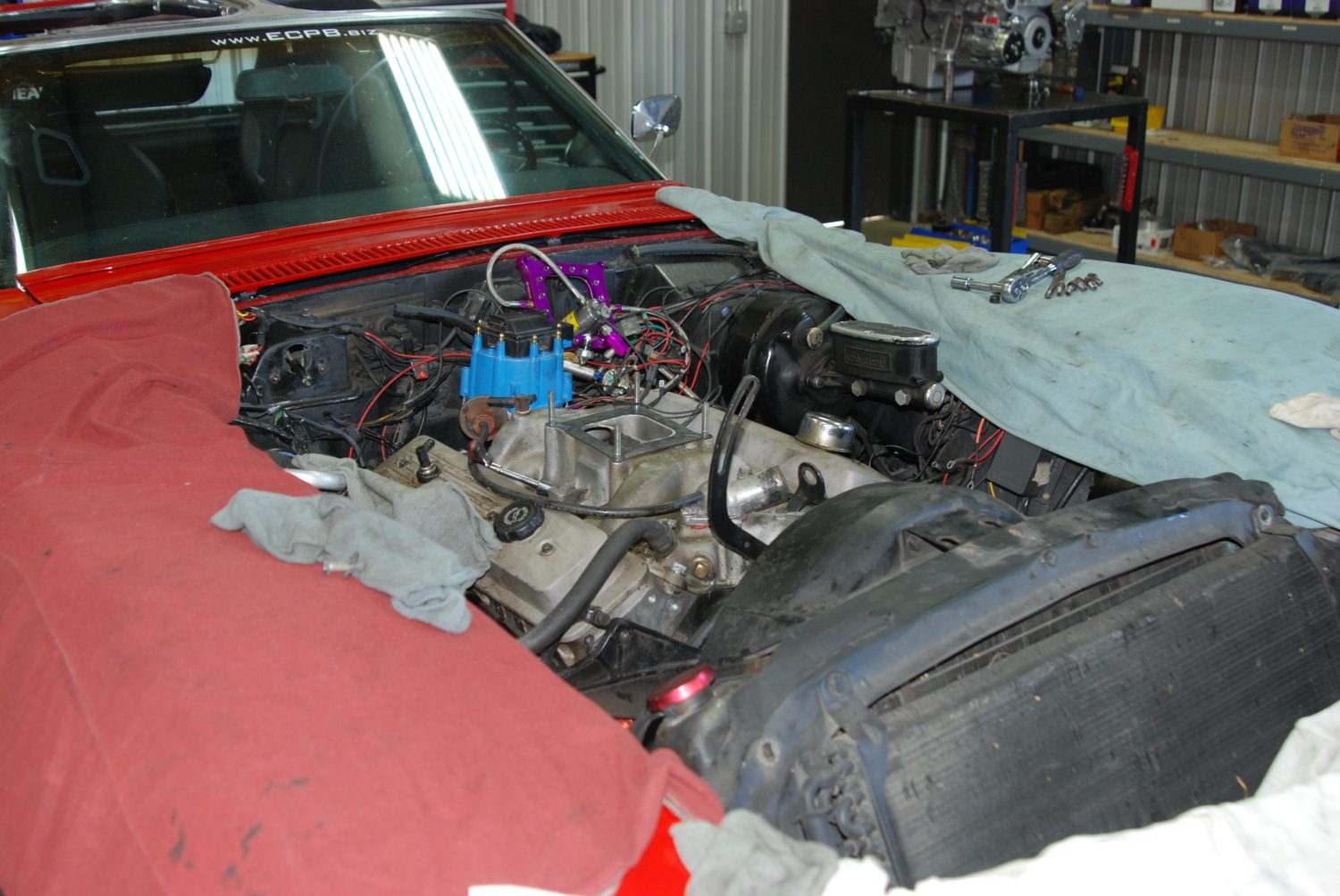
The Holley race carb and other components on the top of the engine (including the nitrous system) come off next.
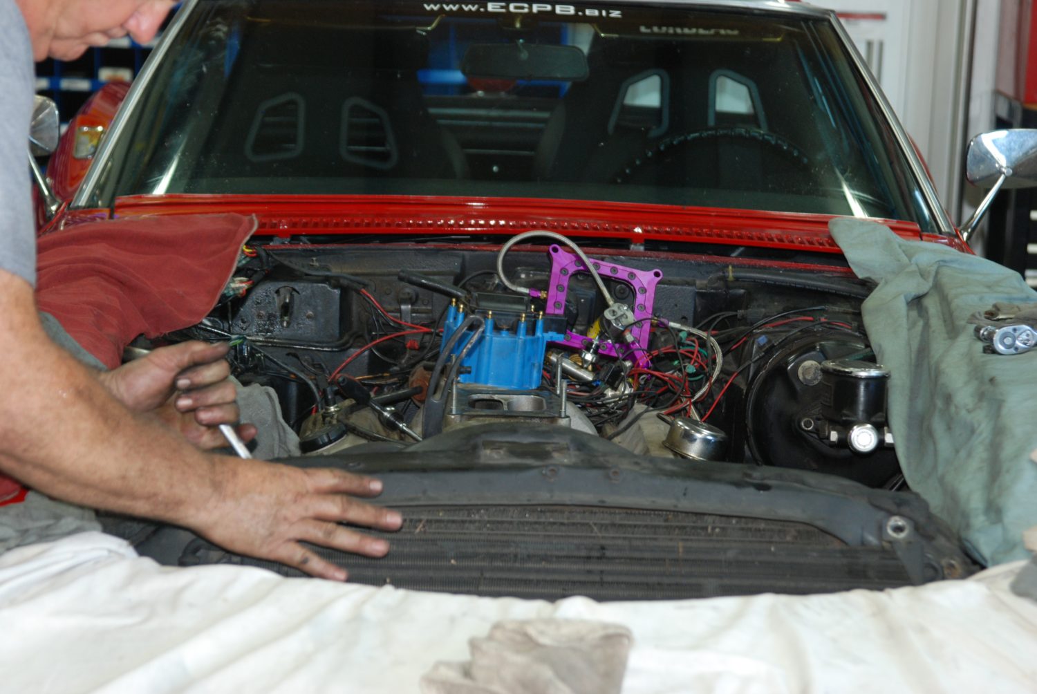
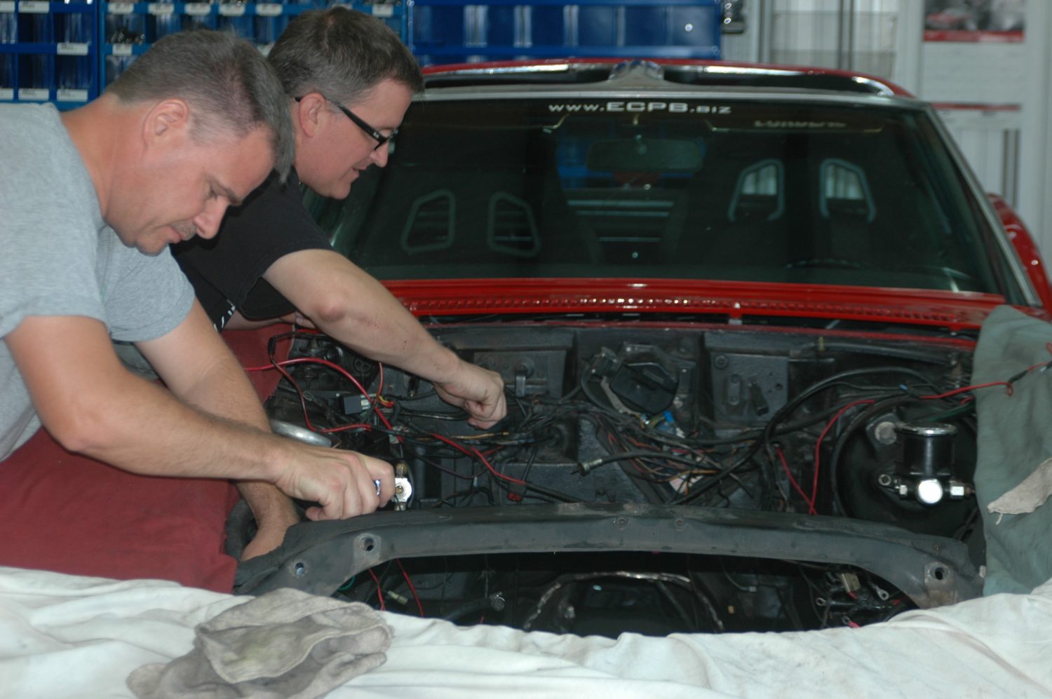
We have to remove the condenser from the factory air conditioning system to loosen the upper radiator mounts.
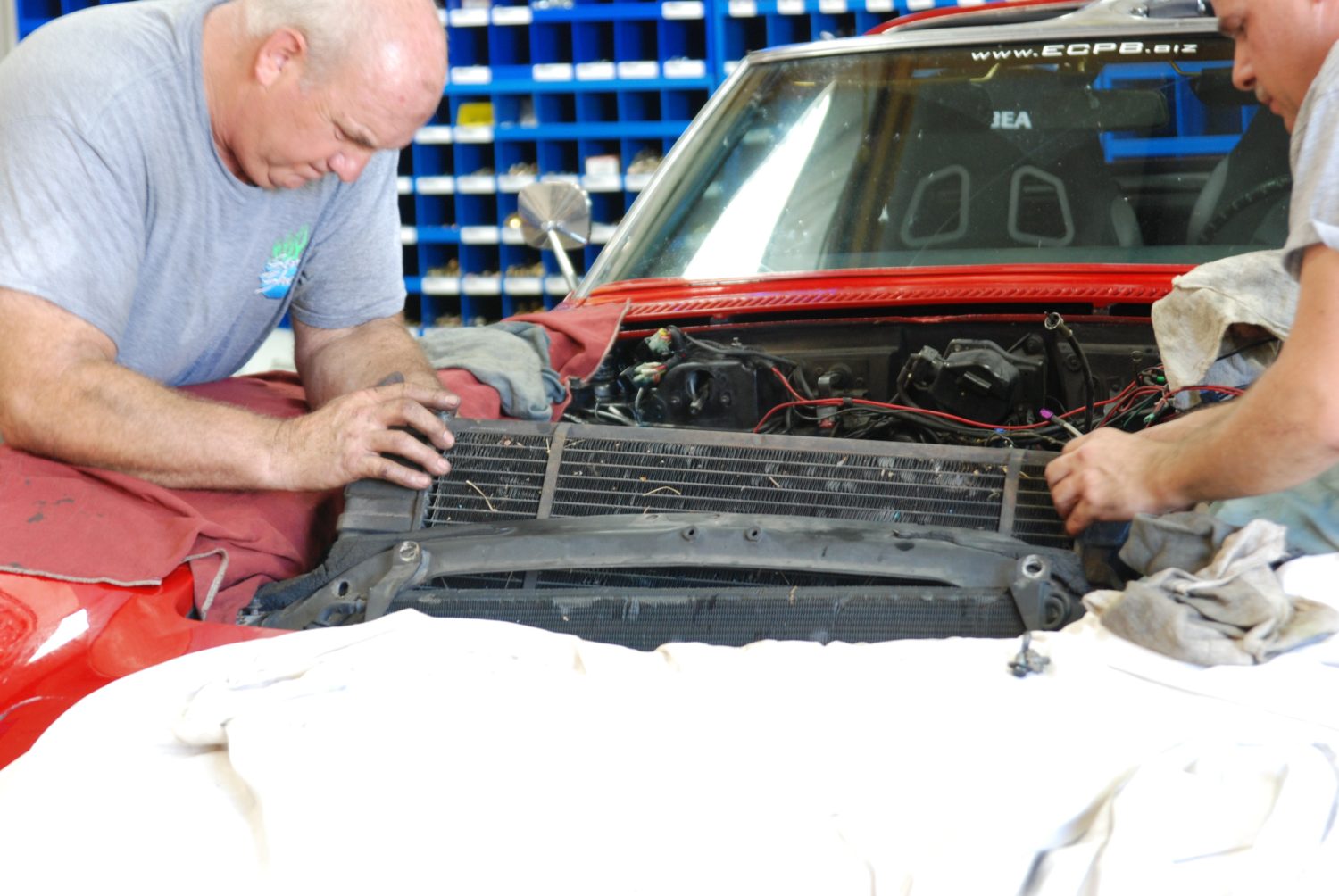
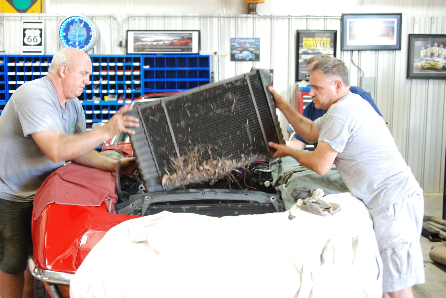
Once the upper mounts and the radiator hoses are removed, tilt back and lift it out—and while I’ve done this job alone, it’s much, much easier to do it with two people to safely ease the radiator out.
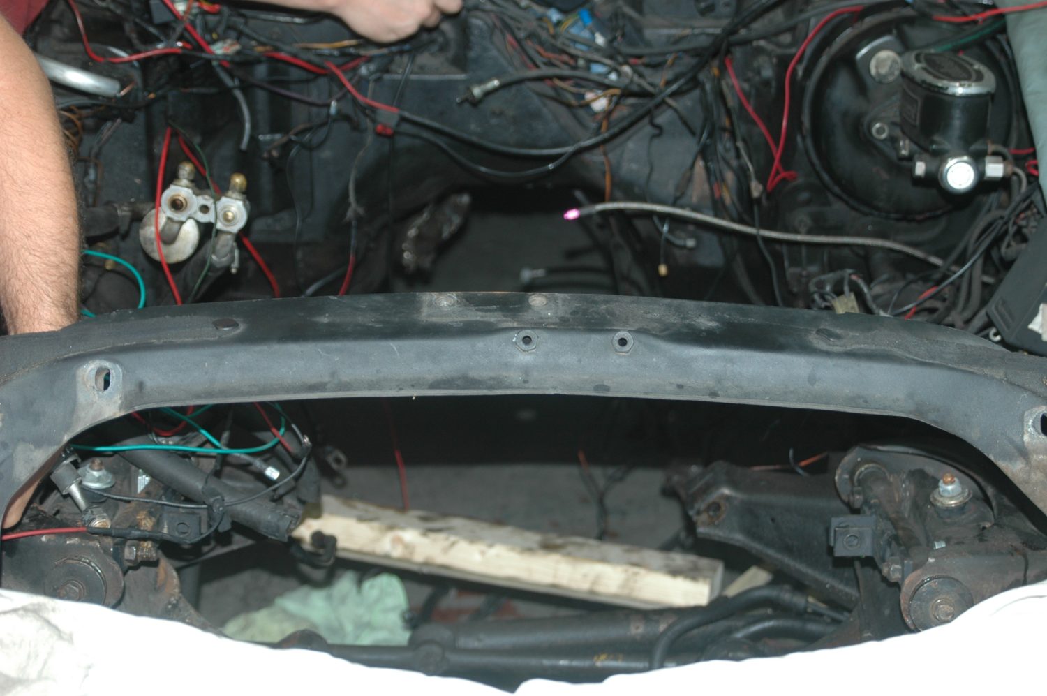
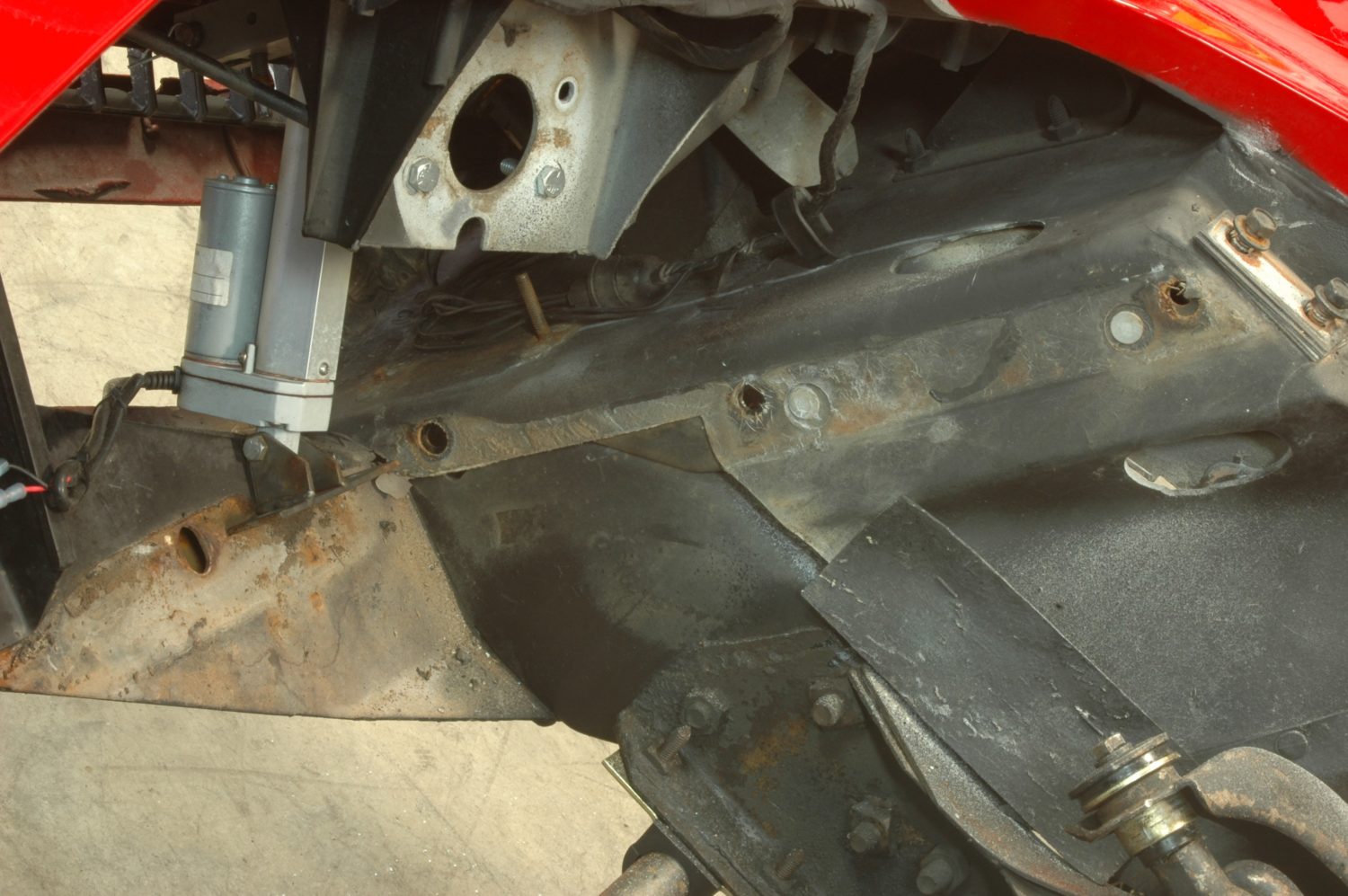
This is what you’ll see once it’s gone.
With the radiator out, it’s time to make quick work of everything else in the engine compartment. Since this is a full rebuild, we leave virtually nothing in place, wiring included.
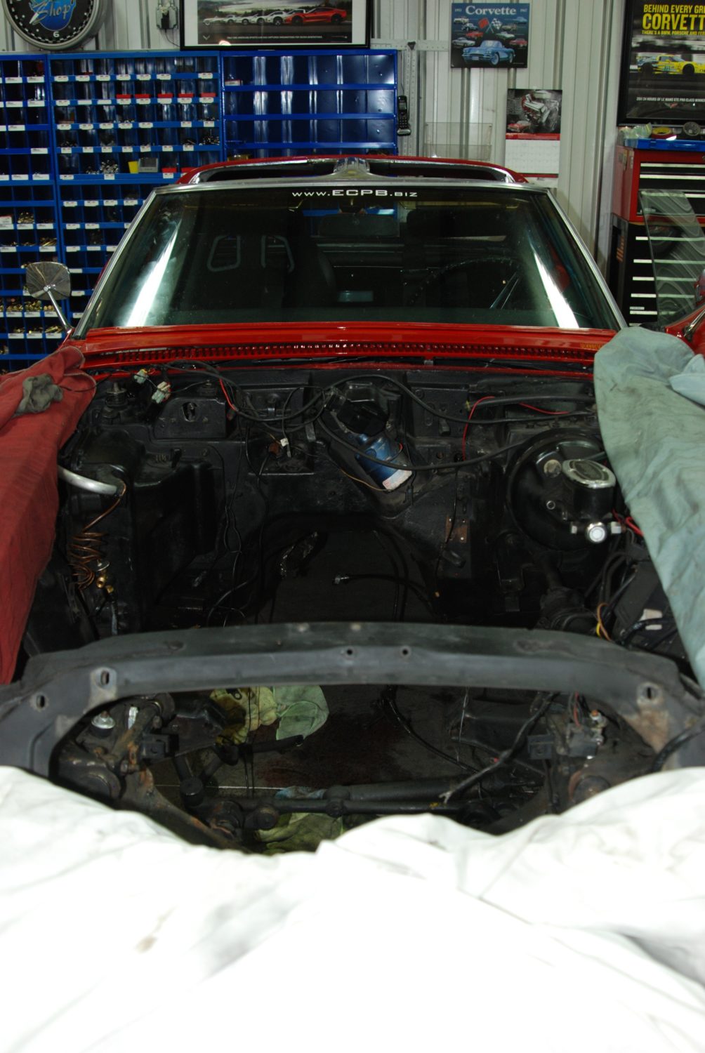
The now-empty engine compartment, ready to be cleaned and dressed up a little before things start going back in.
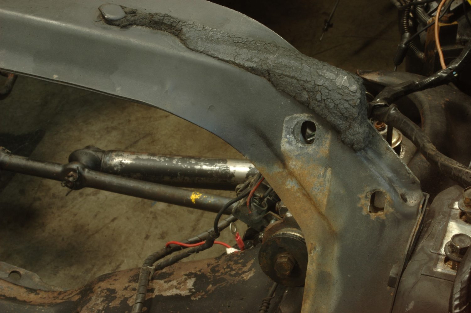
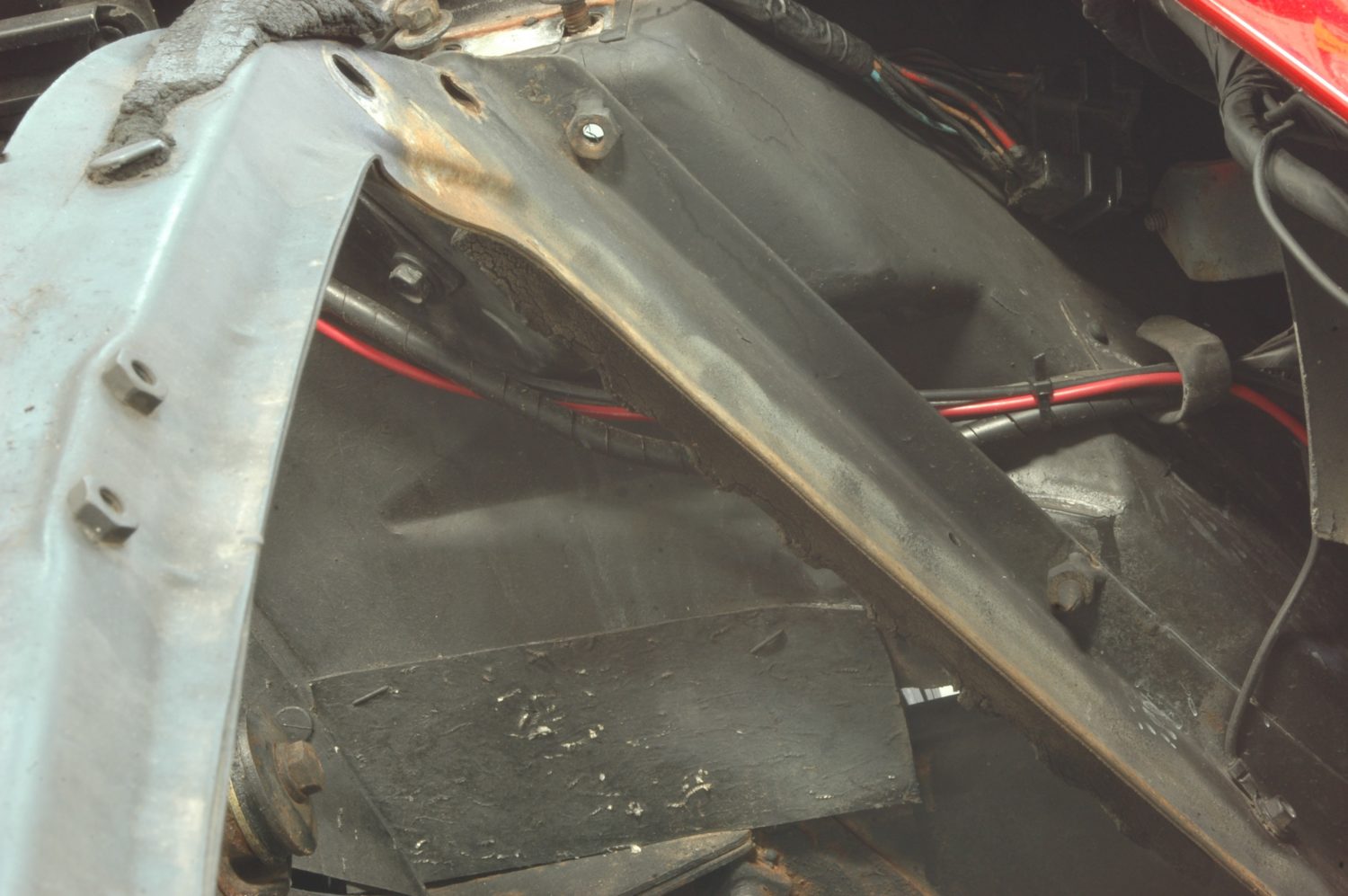
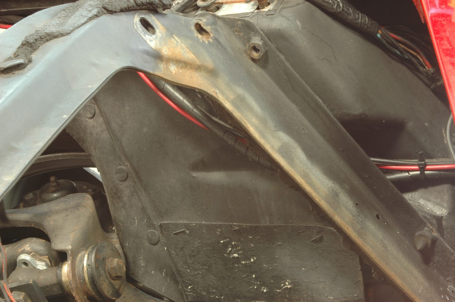
The core support is a classic rust spot, and ours didn’t disappoint. While this is only surface rust, it only gets worse with time. Also note, the foam seal has deteriorated beyond the point where it’s really doing anything.

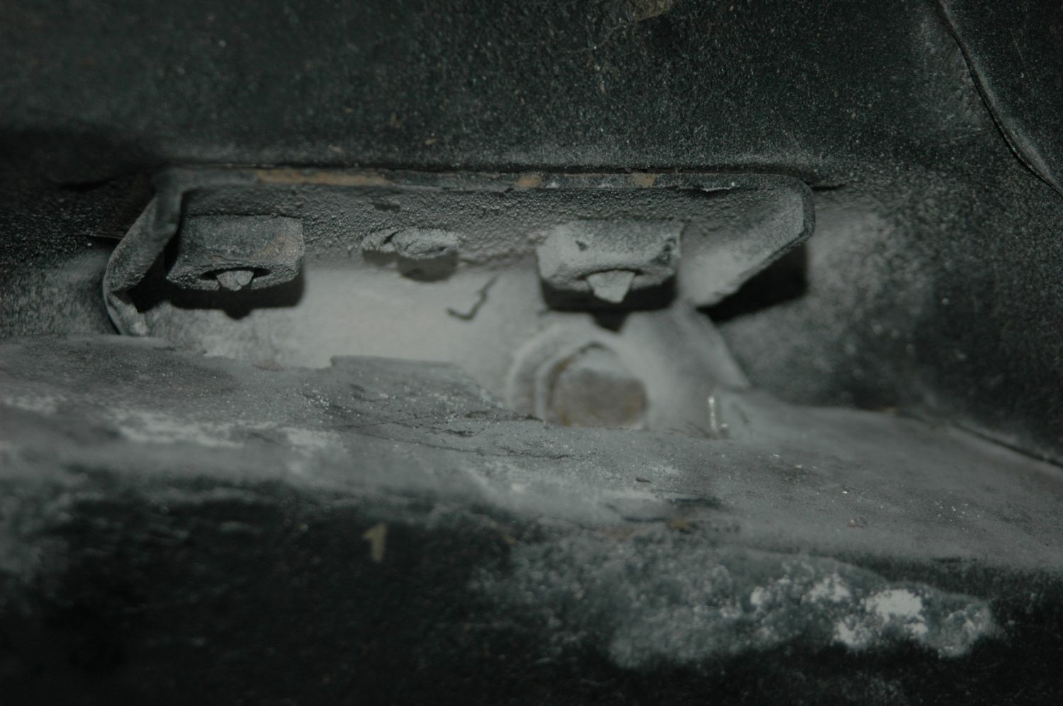
The bottom of the core support, showing the lower bracket and cushion that hold the radiator in place. Also note the ground wire bolted to the support—you’ll want to remove that prior to taking the support out, and make sure it’s correctly reinstalled later.
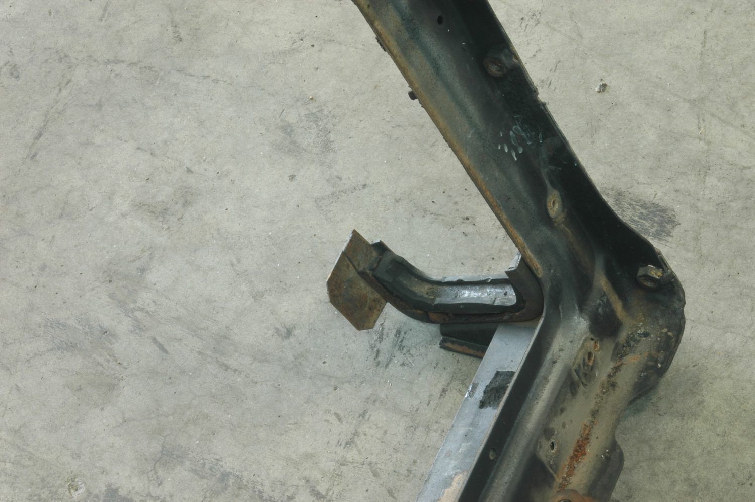
The bottom of the core support, showing the lower bracket and cushion that hold the radiator in place. This is a particularly vulnerable area when the support is shipped—the shipping company bent ours twice—but minor damage can be safely bent back.
The core support is held in place by three screws on either side, as well as being bolted in place at the bottom. In this photo, the top screw on the driver’s side has already been removed.

The screws on the side of the support can be devilishly hard to get to—the screw head in this case is shown behind the bracket with the two screws in it, and we had to trim some fiberglass to get at the screw on the other side.
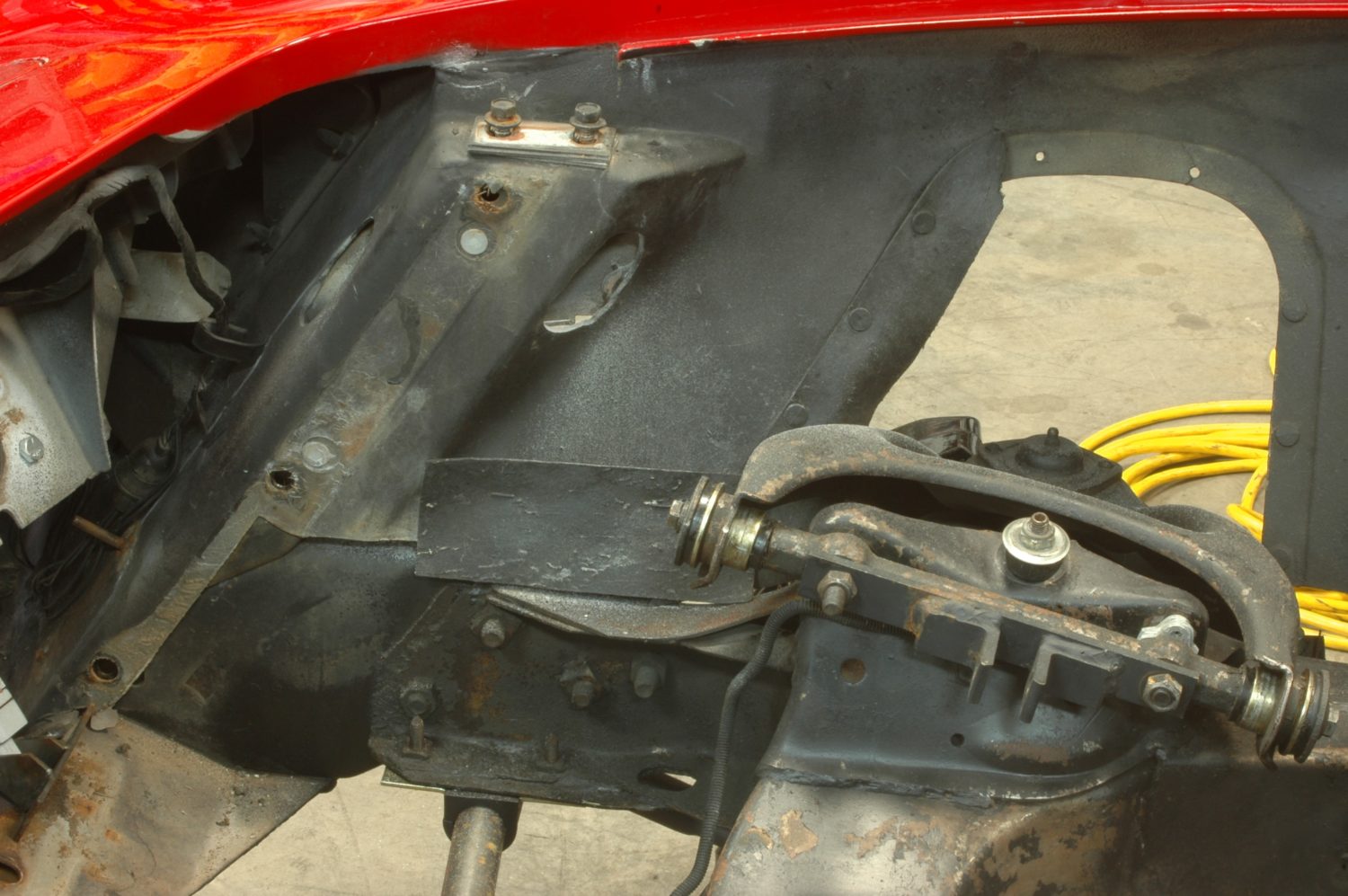
The front of the engine compartment with the core support removed and the holes for the three screws clearly visible. Our screws are rusted, so we replaced them with new stainless ones.

Much better: the new radiator core support, sourced from Corvette Central. Available in more than one size, we chose the big block core support to hold the larger DeWitts radiator required to cool the potent LS.
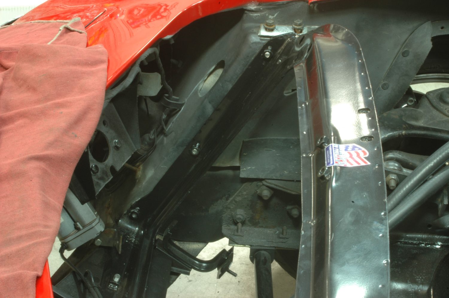
The new core support bolted in place. Be aware, the core support serves as a structural member for the nose of the car, which means the position of the nose may shift once it’s removed. That can complicate aligning all the right holes with the matching holes in the support. We use a tapered rod to lever things into place.
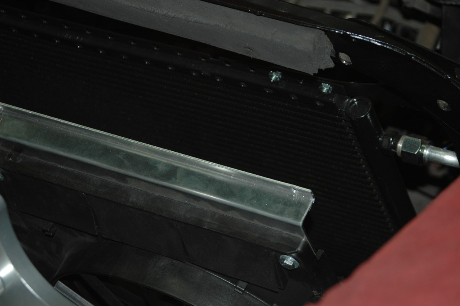
The foam seals, which we also sourced from Corvette Central, in place on the core support. While easy to overlook, the seals are critical to ensure airflow goes through the radiator, rather than around it…which would defeat its purpose.
The rubber cushions in place in the lower bracket. The cushions are the same for top and bottom, and have tabs that slip through holes in the bracket, holding them in place.
The extension to the side of the lower bracket is unnecessary for our purposes, so we cut it off. Dress the edge of the cut to remove any jagged edges, finish with some black spray paint to ward off corrosion, and you’re good to go.
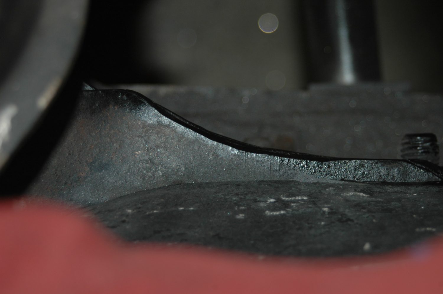
Because the radiator and fans we use are substantially larger than a stock radiator, we have to do some cutting and grinding in order to get clearance for them to slide down into place.
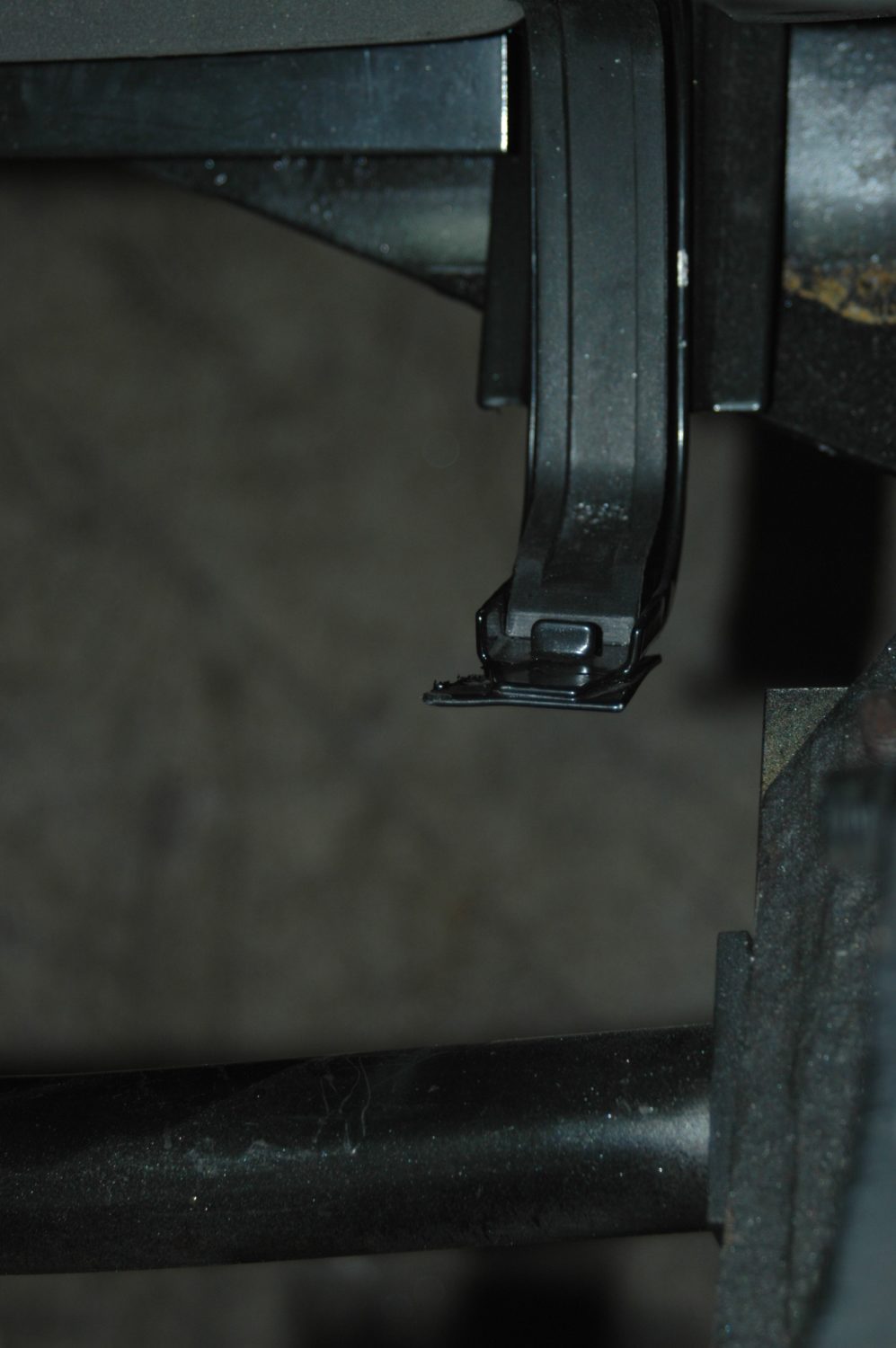
Unfortunately, we need more than clearance for the radiator to fit: ours has to go back home for modification in order for the lower neck to clear the frame.
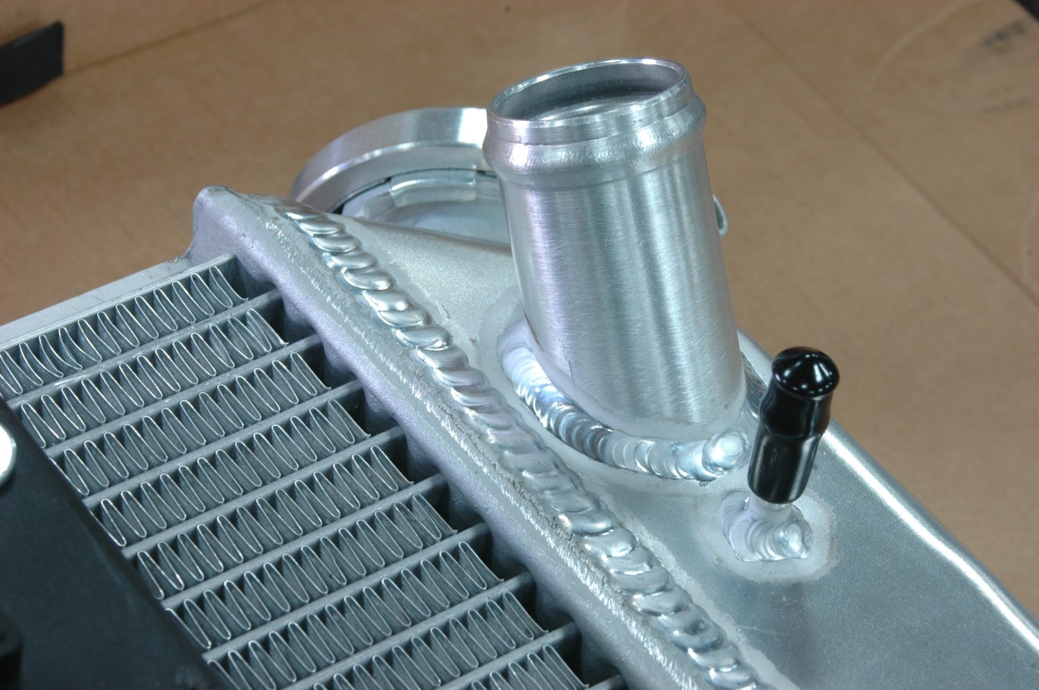
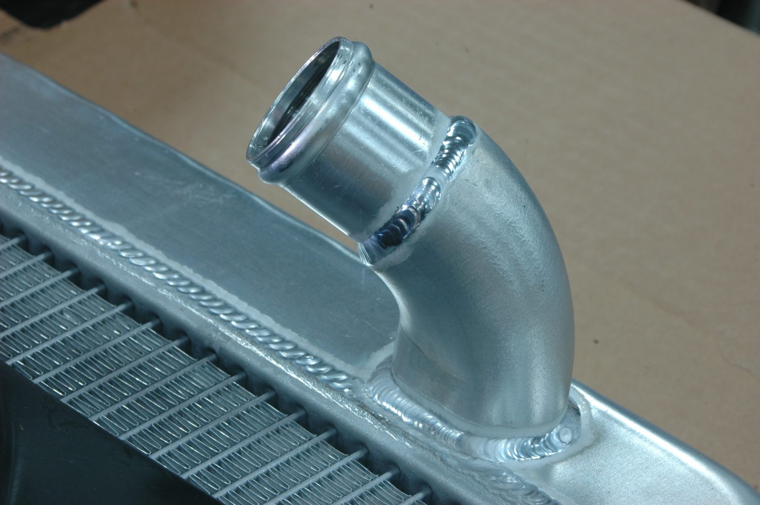
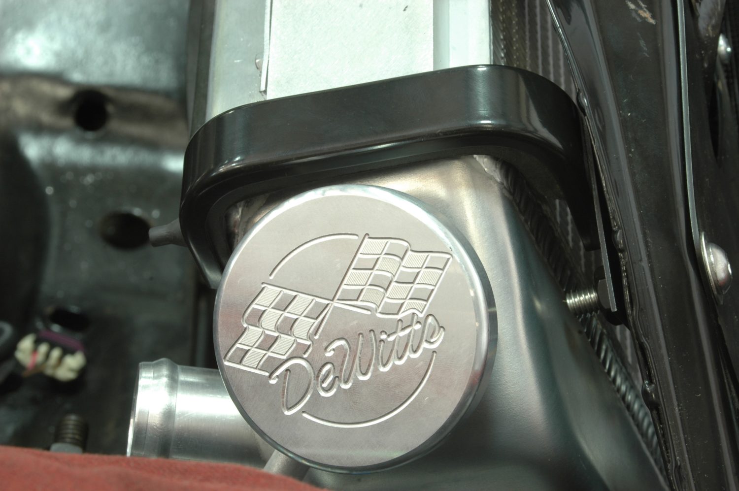
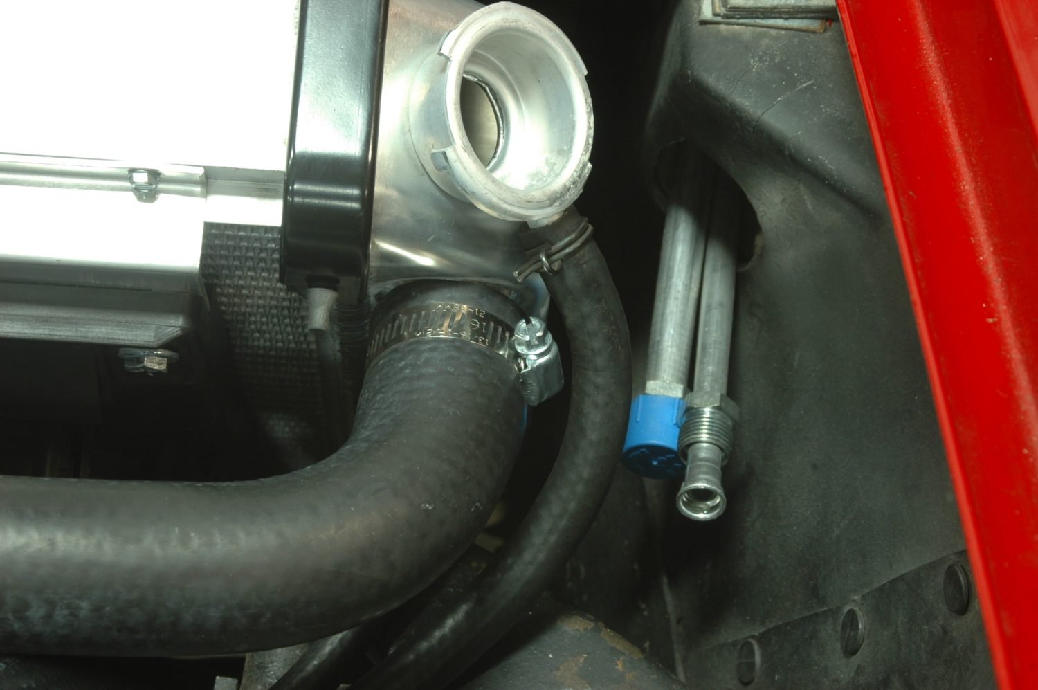
The top of our aluminum radiator, showing the upper neck and the nipple for the steam line, which, along with the change in neck location, is a dead giveaway for an LS conversion radiator.
Due to the space constraints of putting in the radiator with the engine already in place, we have to remove the fans from the radiator and lay them loosely in place before we can slide the radiator down between them and the core support.
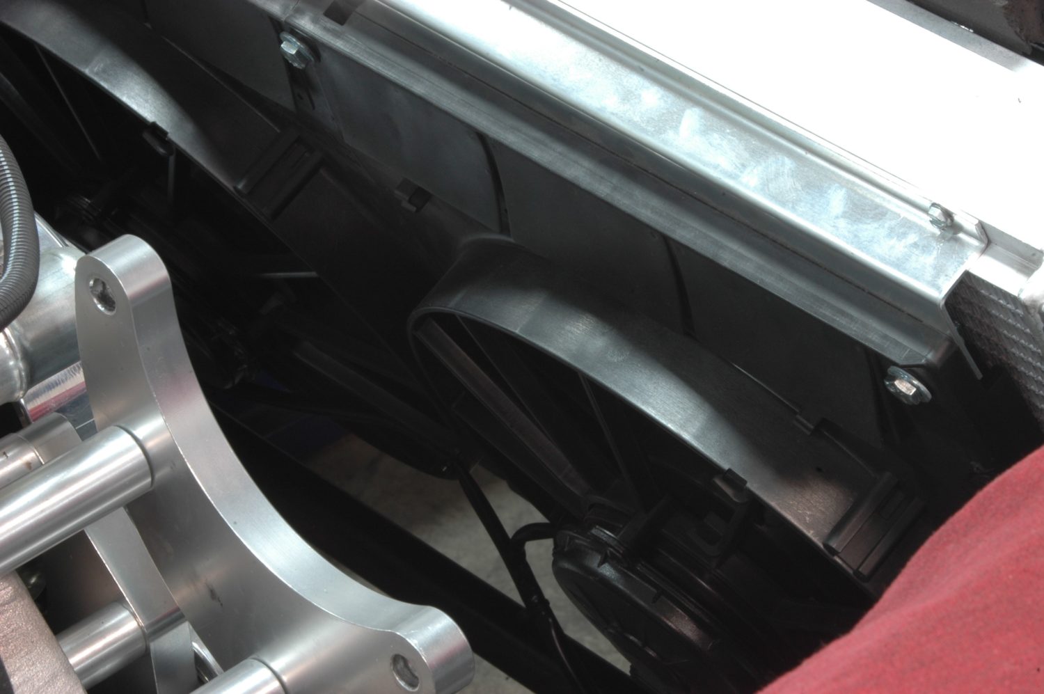
Once the radiator is lowered into place in the cushioned lower bracket, we pivot the fans forward and screw them back into place on the radiator.
The filler neck on the radiator once it’s been seated in place. Now, time for the upper clamps to go on: one of the mounting holes is visible in the lower right part of the photo.
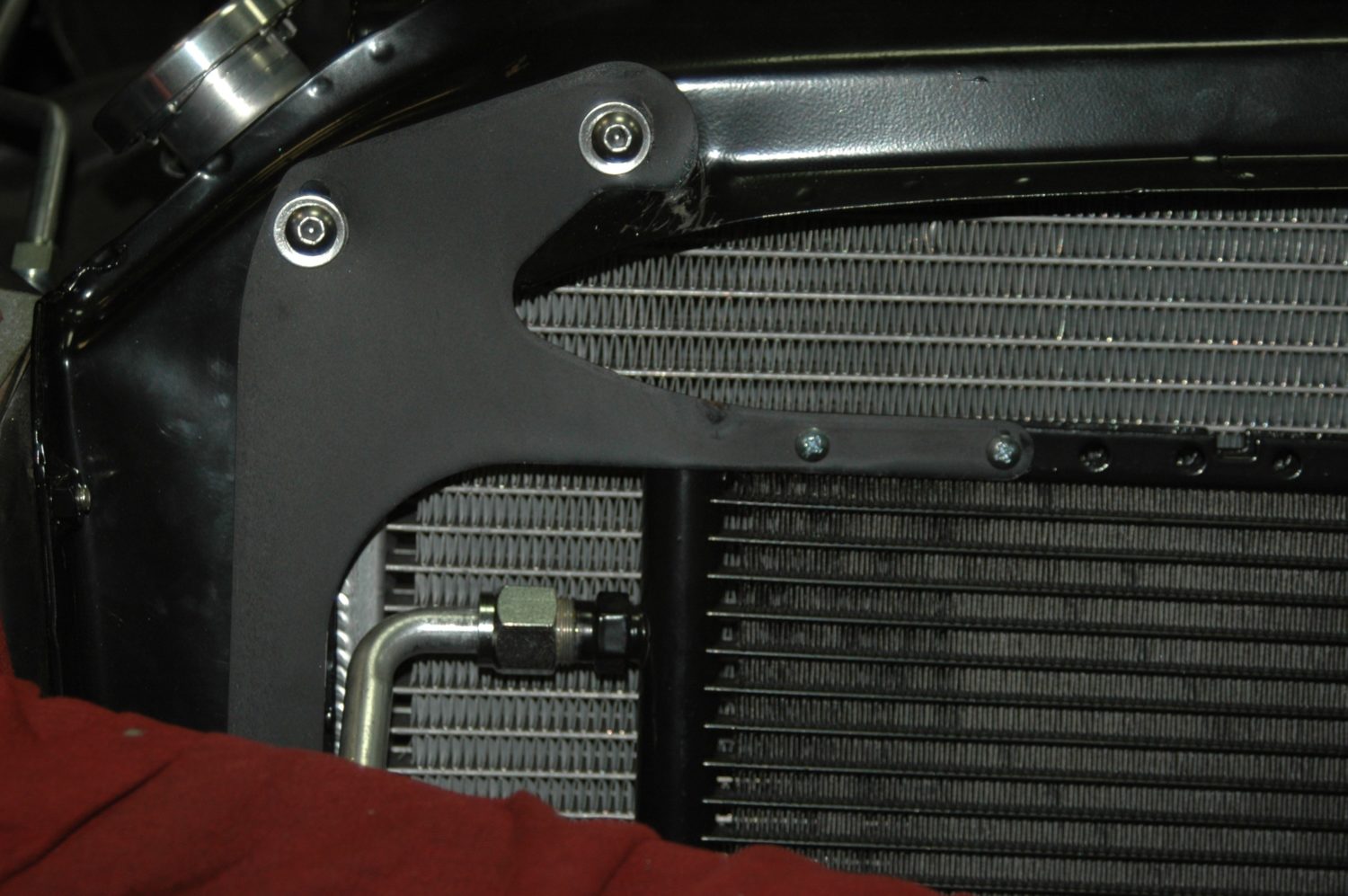
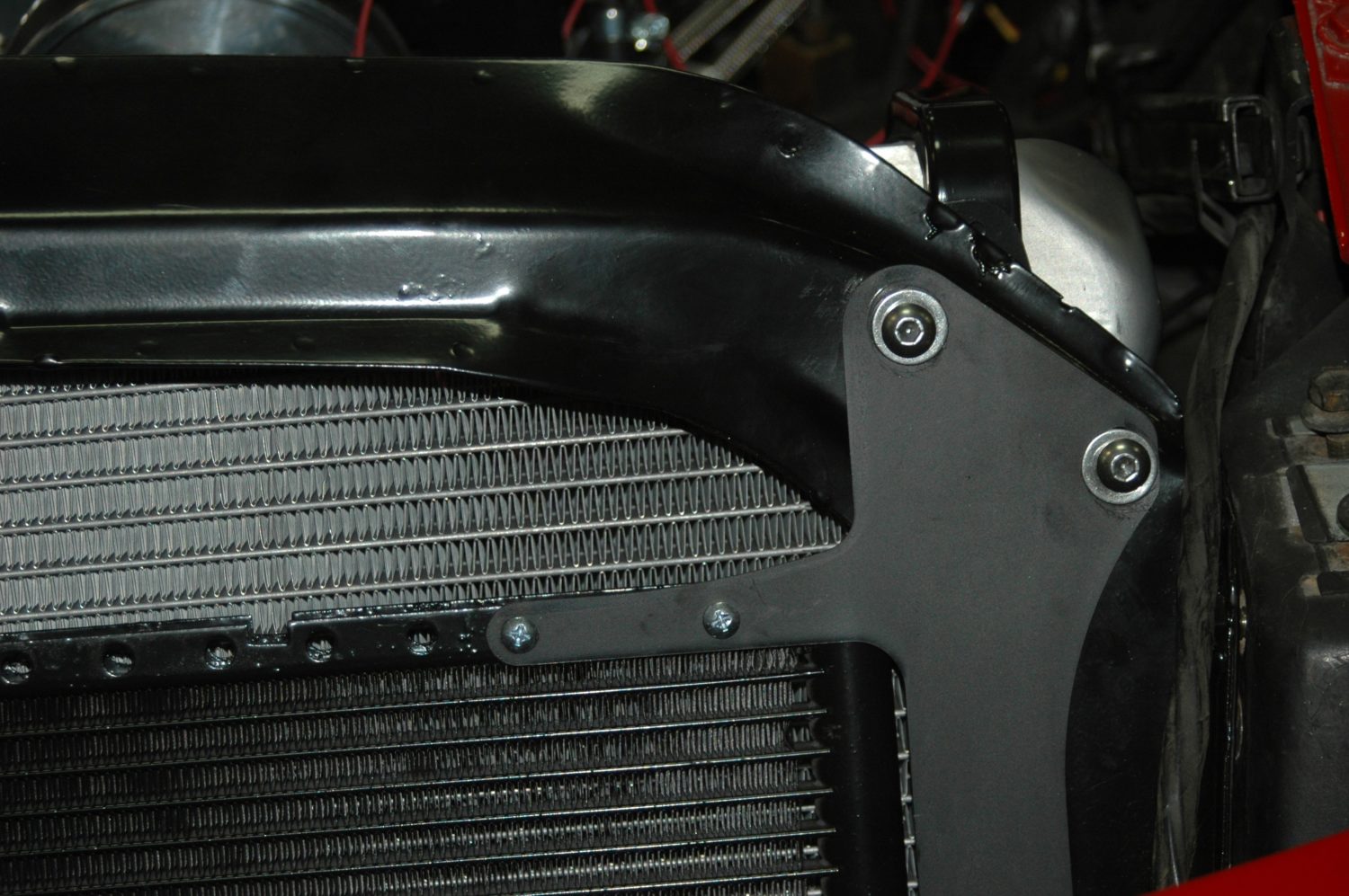
We use stainless screws to mount the upper bracket, and run them through matching holes into the bracket that holds Vintage Air condenser in place on the front of the radiator.
Once fully installed, our screws are too close to touching the radiator than we’re comfortable with, so they have to be shortened.
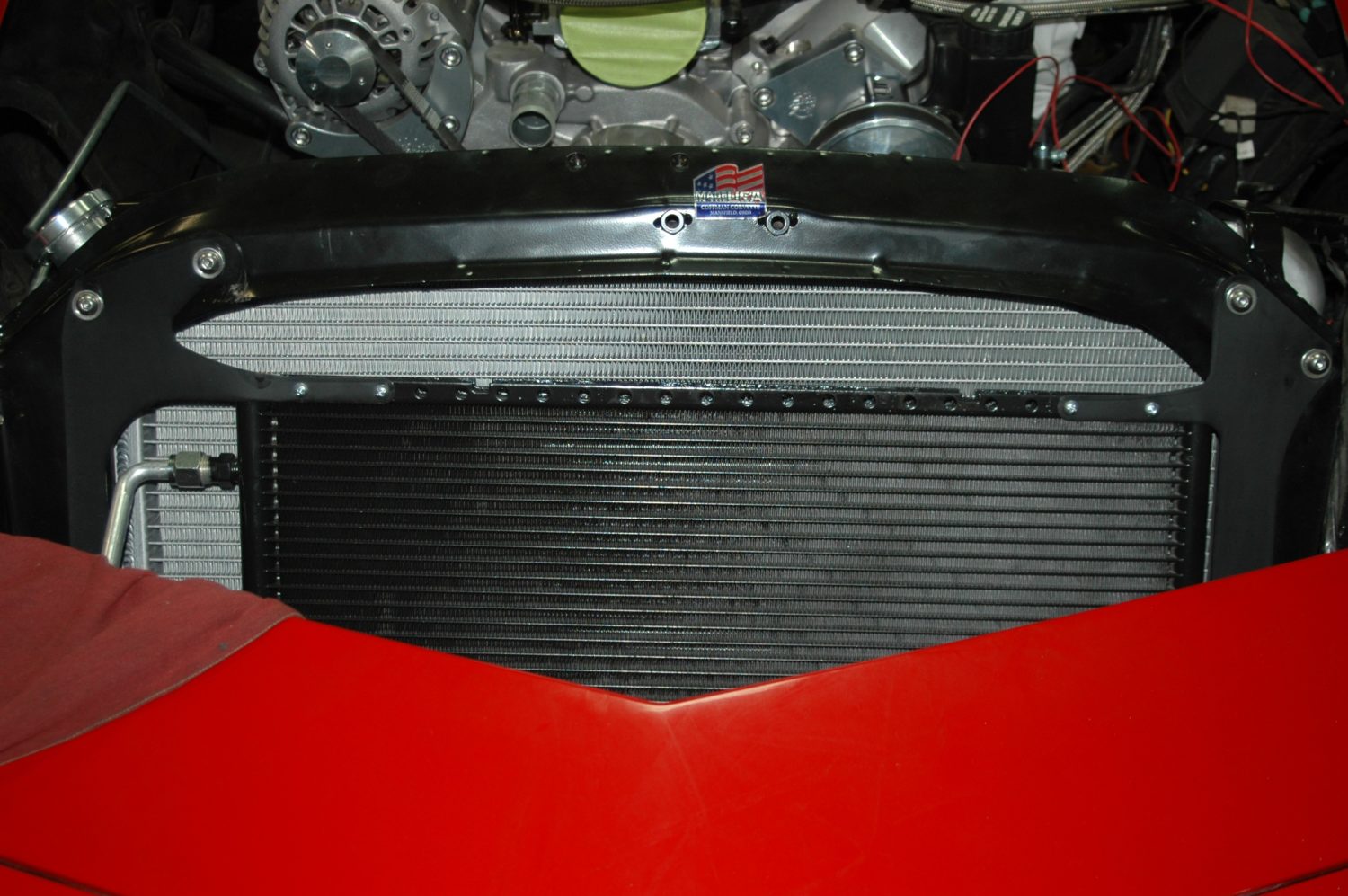
The radiator, core support, and condenser after installation is complete.
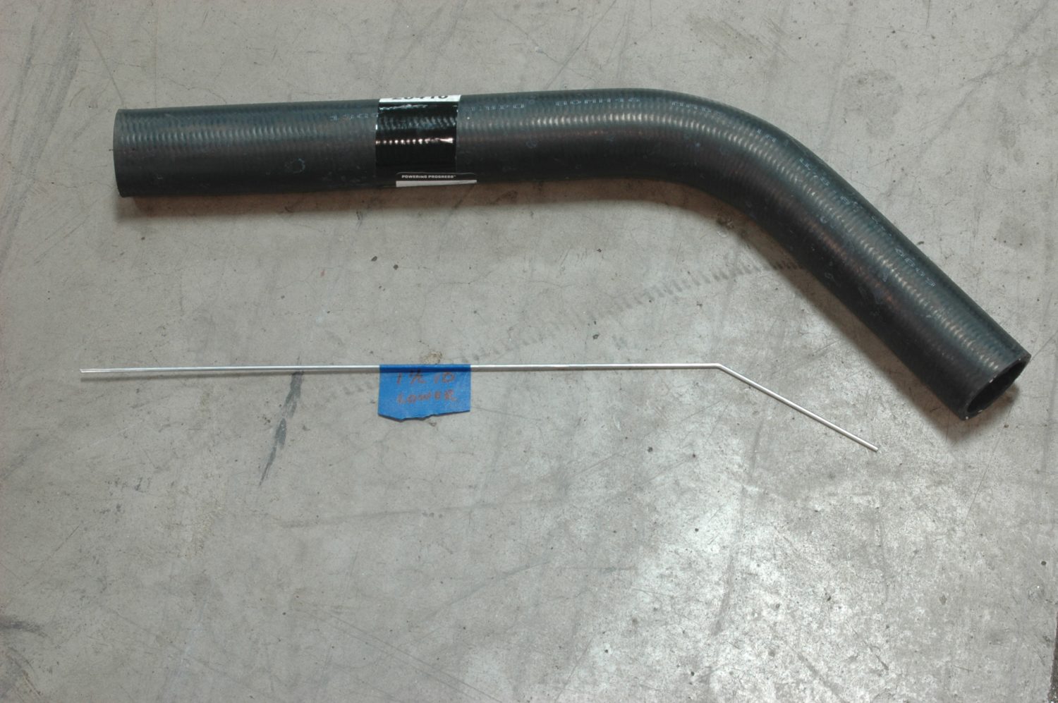
The lower radiator hose. Since there is no factory option for an LS installed in a ’72 Stingray, we usd a piece of bent wire approximating the path and length of the hose, then use that to pick the hose that looks closest. Write down the part number, since the bent-wire option may not work if you wind up on the side of the road.

The upper radiator hose, along with its bent wire.
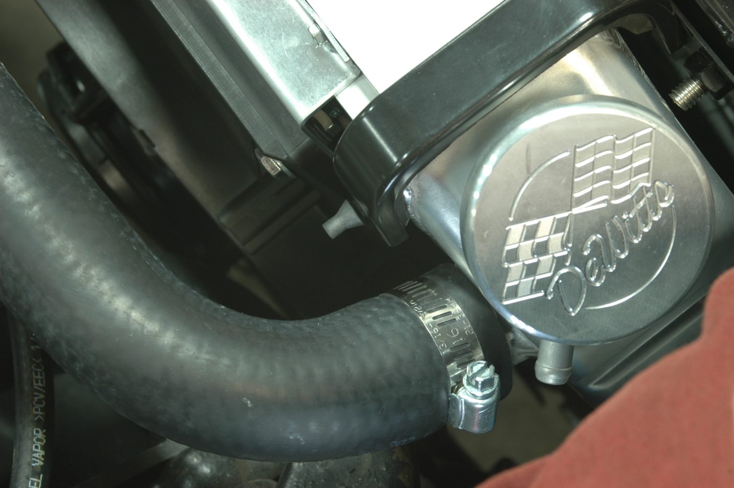
We use traditional hose clamps to mount the upper and lower radiator hoses. Note the nipple for the overflow: we’ll get to that after the steam line.
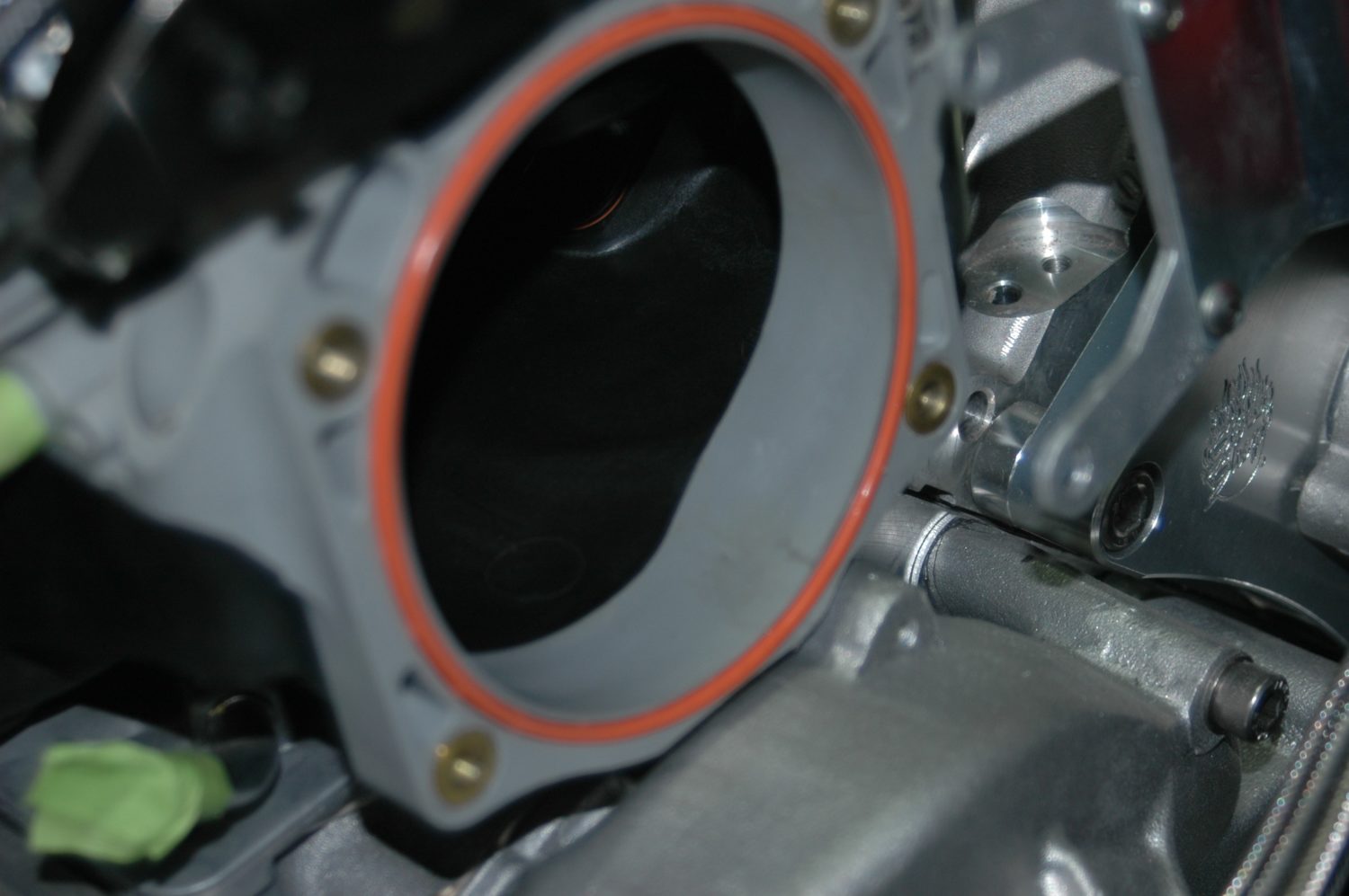
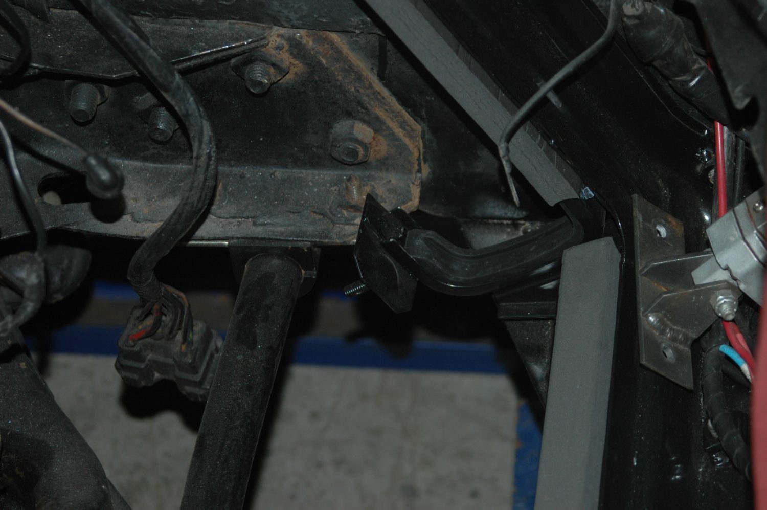
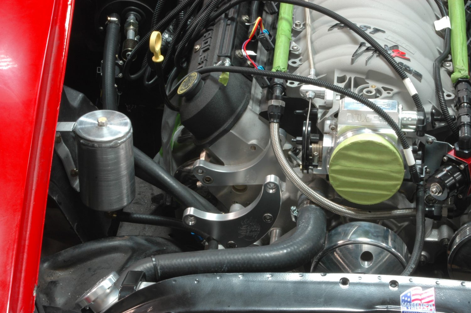
The steam line (we use a factory one with hard lines) routes under the throttle body, and the driver’s side of it mounts to the pad visible in the upper left of the photo.
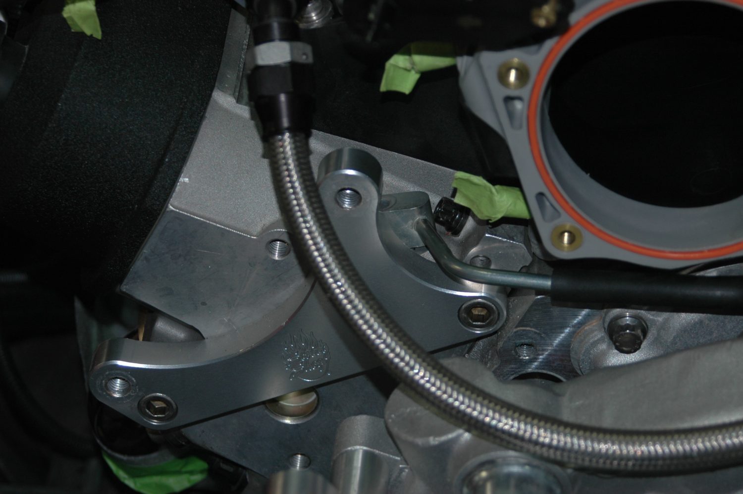
The passenger’s side mounting area for the steam line with the line’s mounting pad partially visible behind the bracket for the serpentine belt system.
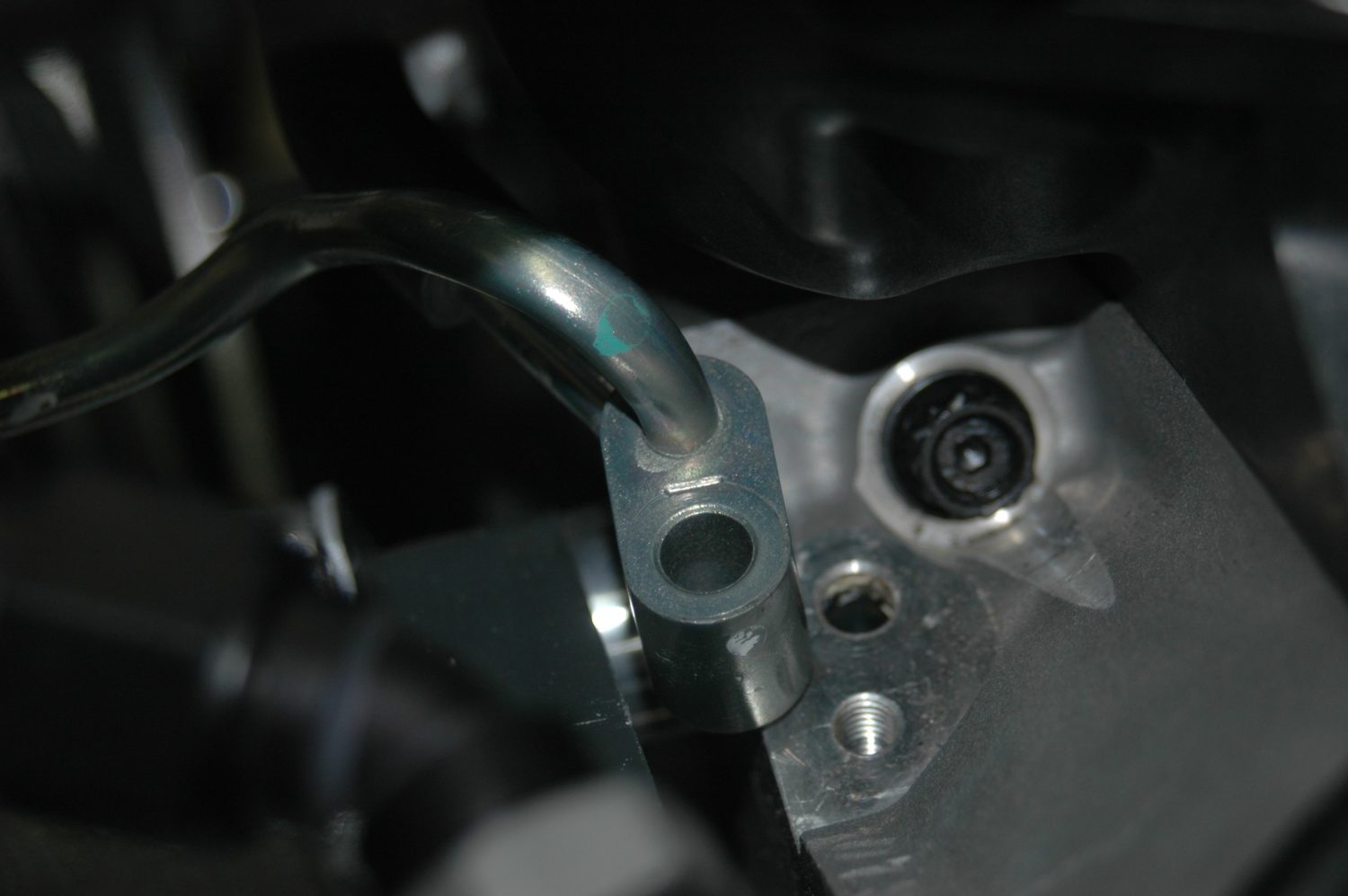
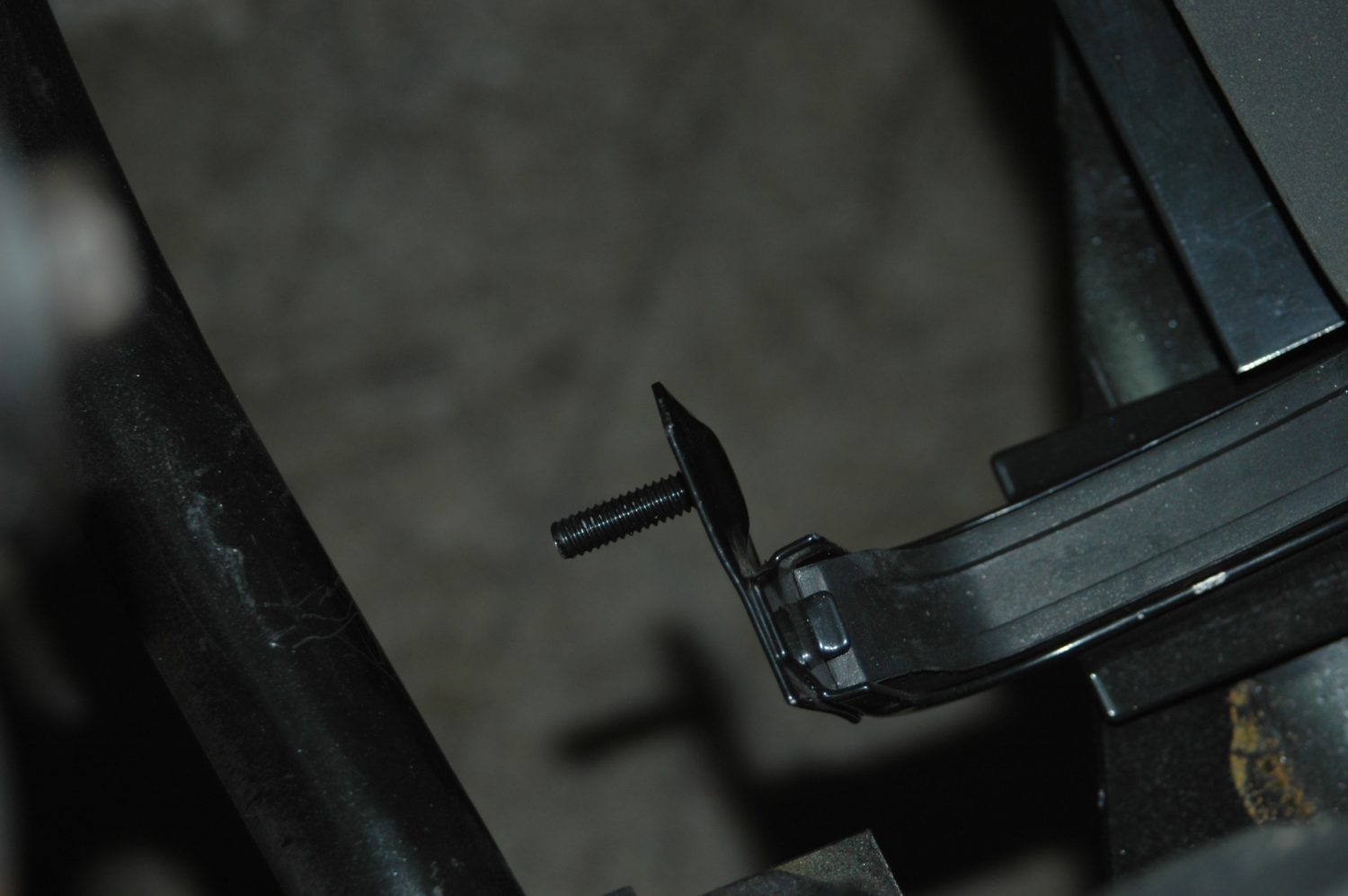
How the steam line is seated on the head: the rear of the mounting block seats against its hole in the head, while a mounting bolt passes through the block and screws down, holding the steam line in place.
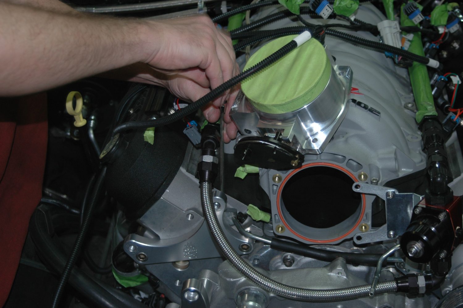
Screwing down the mounting bolt on the passenger’s side of the steam line. Note, we had to remove the FAST 102mm throttle body in order to locate the hard steam line in position.
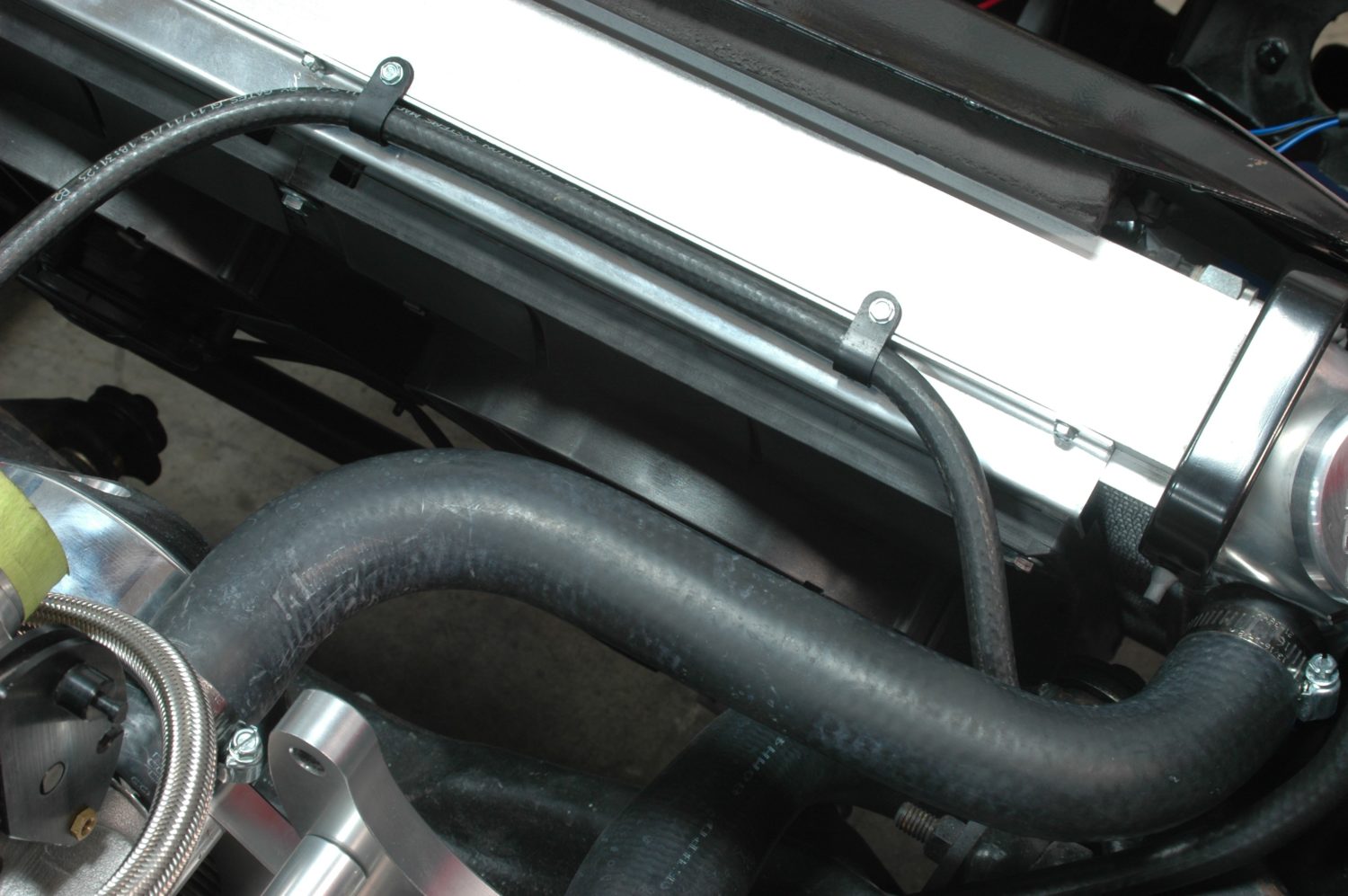
Once the hard line is in place, we use a length of hose to connect its outlet to the radiator, routing it across the top of the fan bracket. We hold it in place using a pair of hose mounting clamps screwed directly into the body of the radiator, after making sure there is enough material here to do it safely.
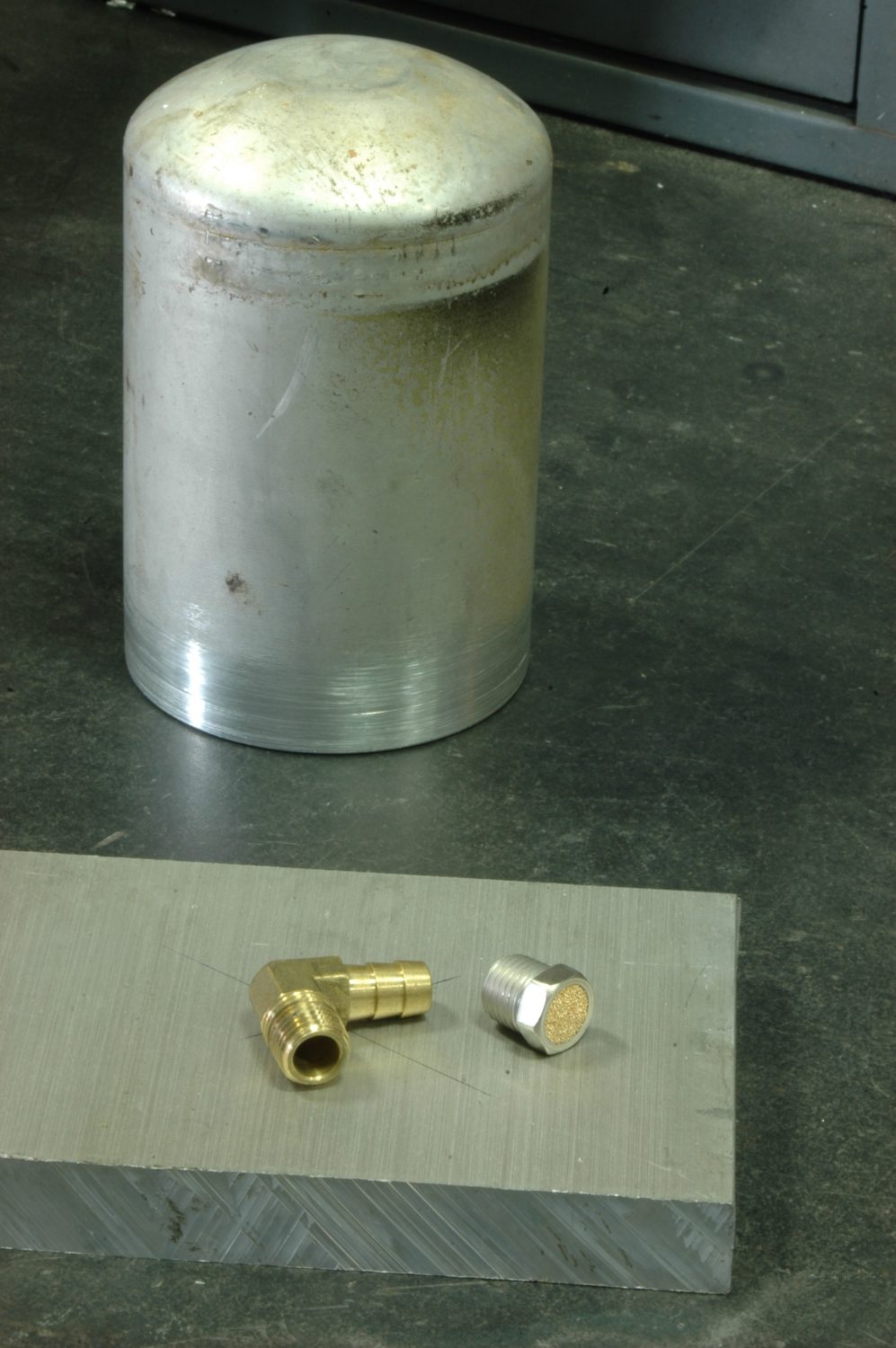
What we start with to make an overflow bottle: a block of aluminum, an unused aluminum bottle, and the fittings for the top and bottom.
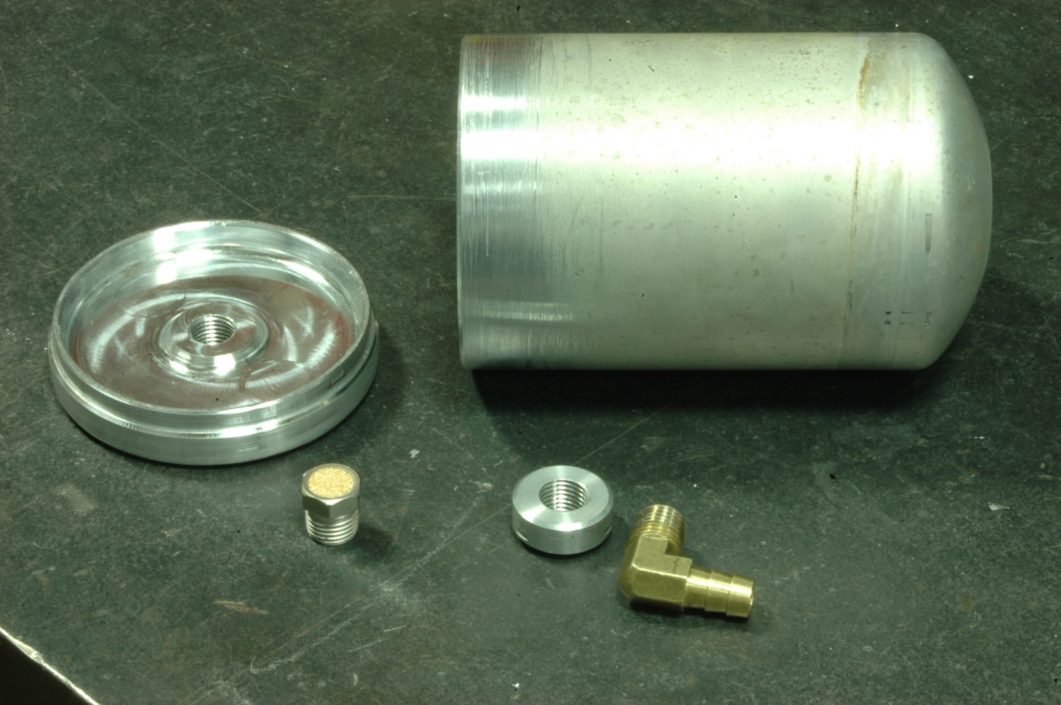
The bottle and fittings shown with the two pieces we machine for it: a threaded bung for the bottom which I turn on the lathe, and a cap that Tray Walden designs in CAD and cuts on the CNC mill.
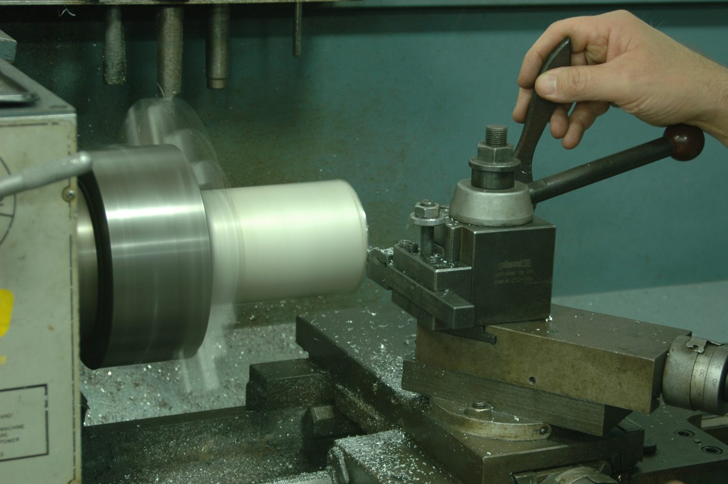
Turning the aluminum bottle on the lathe to true it up and prepare it for welding.
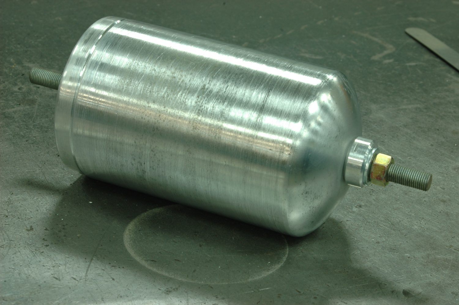
Prior to welding, Tray runs a threaded rod through the cap, bottle, and bung to keep everything in place once we put the heat to it.

Tray Walden welding up the bottle.
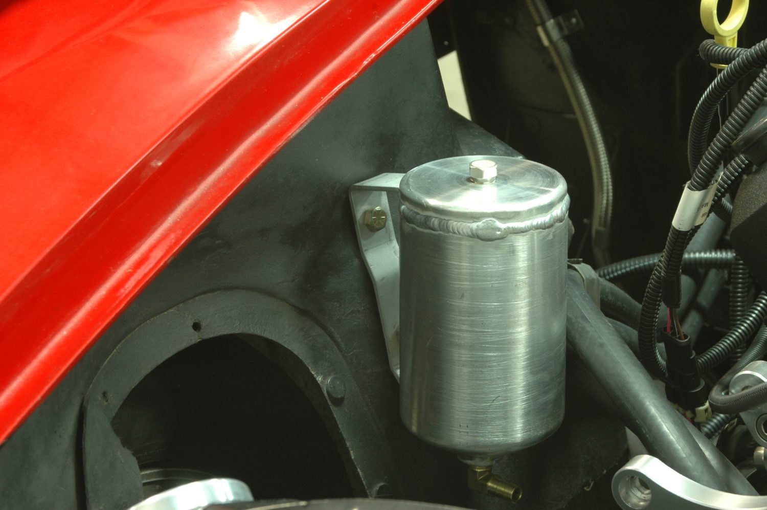
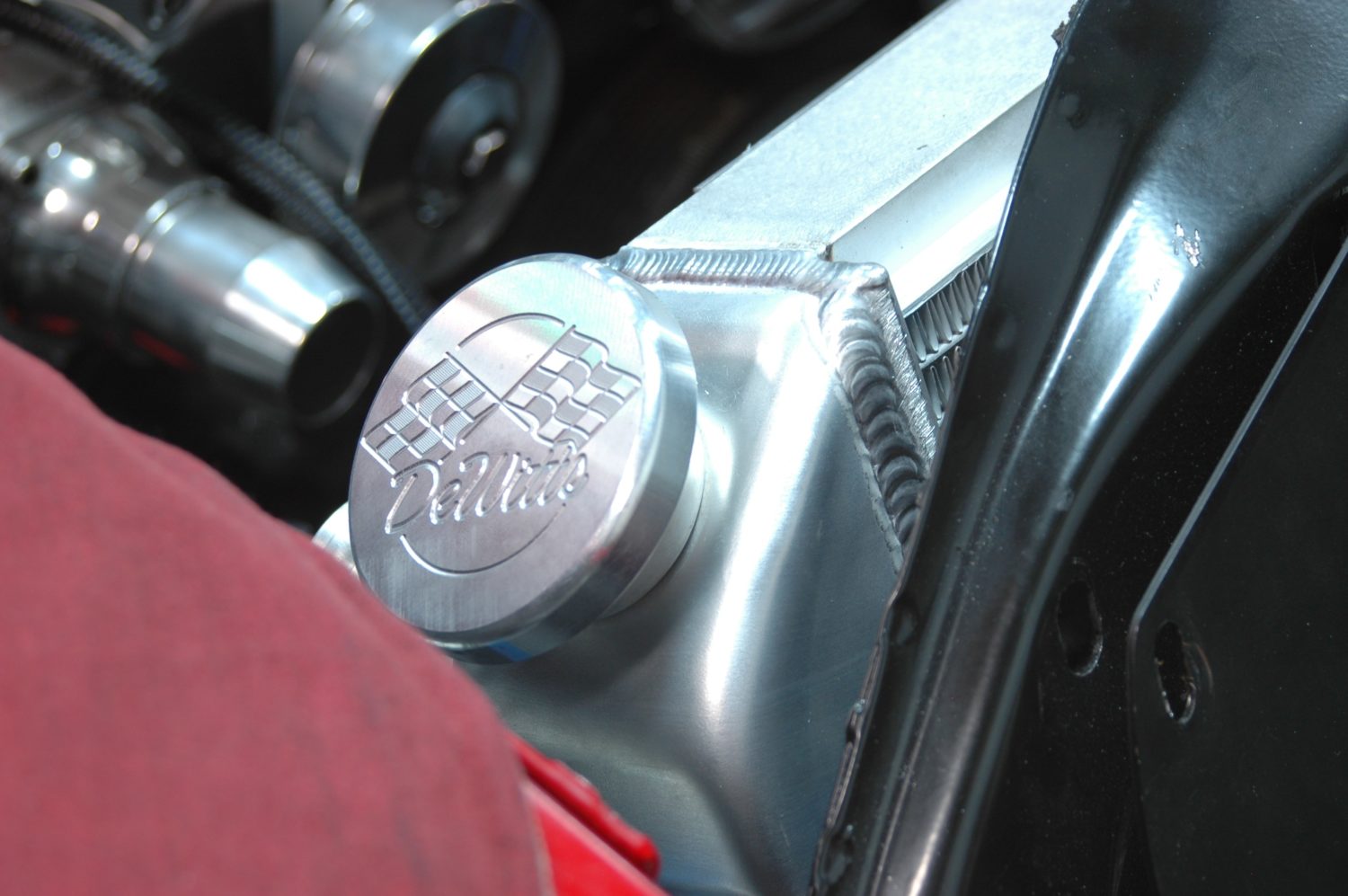
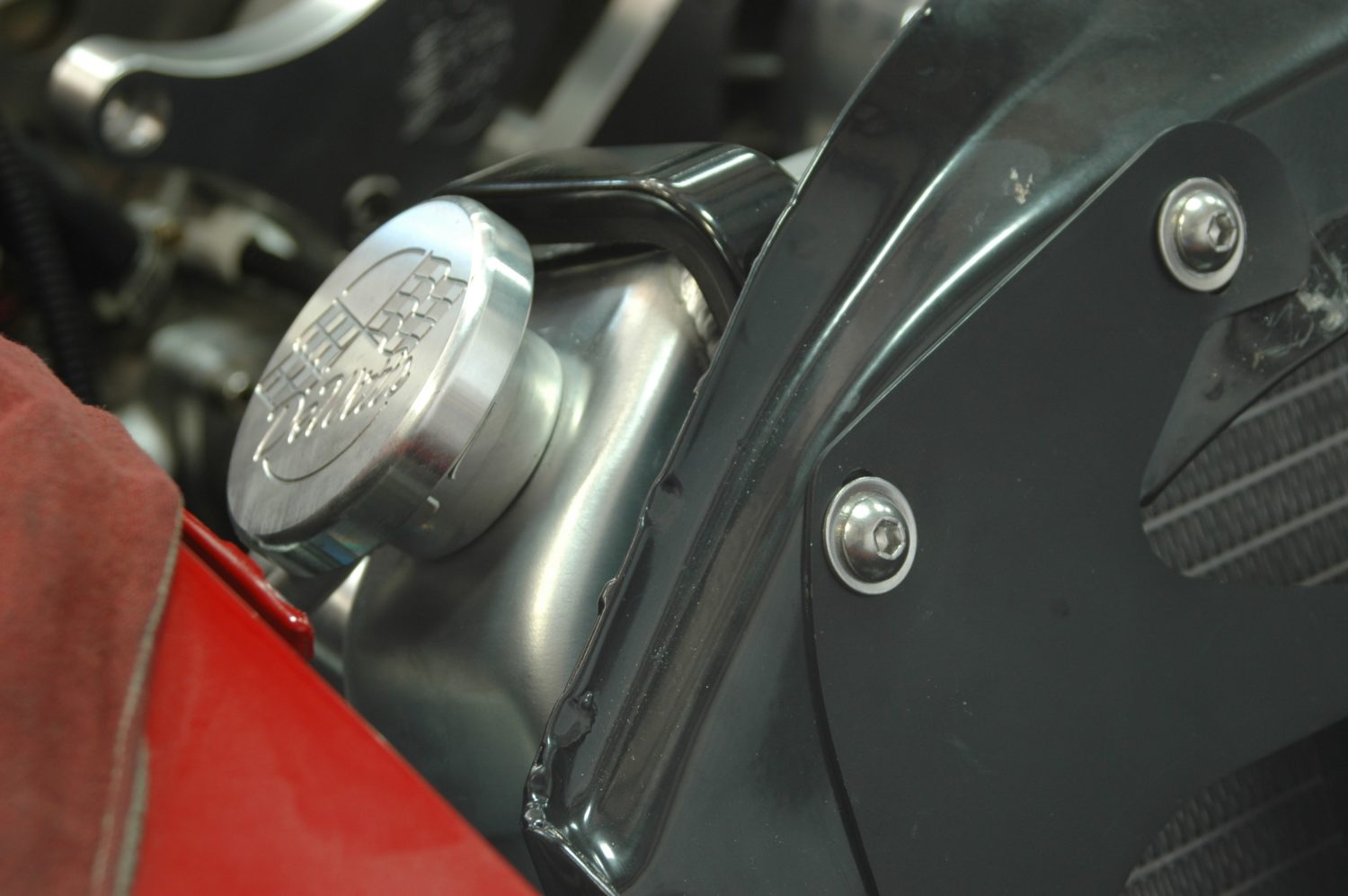
The finished bottle mounted in place on the inner fender. Now that’s built and we know it fits without need for modification, off it goes to be polished.
The bottle in place and with the hose, visible beneath it, mounted to the lower fitting, which is a brass 90° fitting with a hose barb.
The overflow line mounted on its nipple on the radiator.
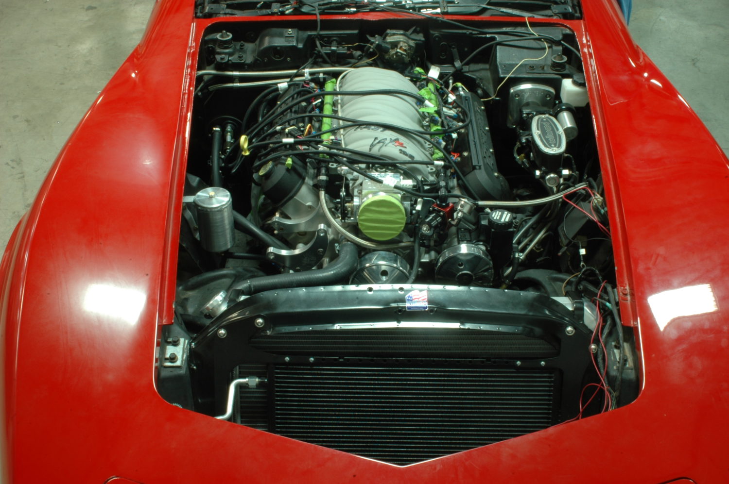
The cooling package complete: radiator, fans, hoses, and both steam and overflow lines installed. Everything required to keep that monster LS cool as well as controlling any little mishaps along the way.
Story and photos courtesy Jeremy D. Clough
I have a 76 with ZZ4 crate engine, Automatic tran. AC, would like to go with aluminum radiator and electric fan. What system do you recommend?
Check out https://www.corvettecentral.com/243113.
Thank You,
Product Assistance
Corvette Central
looking to do an LS swap on my 1985 C4 TPI. Besides the cooling issues are there going to be any other roadblocks that’s going to prohibit me from enjoying my beautiful toy?
Hello do you have a bigger Dewitt radiator that will fit my 93 LT1 C4 corvette? I’m putting a chip in the ECM that its supposed to kick the cooling fans on sooner so the engine will run cooler and with the factory radiator its not going to work because its designed to run hot I want to lower the temperature i’d like to get a bigger radiator from you guys
Yes, we offer the Dewitts Direct fit radiator for this. For automatic use 244492. For manual use 244025.
One problem to address is the thermostat housing/neck: factory has the neck pointing in the 9 o’clock position. Often, this is directly facing the passenger-side upper control arm. The housing either needs to be cut, clocked to a different angle, and welded up; or need a part number for a housing that points directly out. Can anyone address this and give a possible part number or source-vehicle remedy? Thanks.
If i am installing this motor in my engine bay, do i need to add any gussets anywhere to handle the added stresses of a higher hp and torque?
As long as you don’t have any serious rust you shouldn’t have any issues.
I have 1980 corvette and put a 572/647 hp 760 fp of torque. My problem is overheating. Do you think this rad will help cool it down? I’m getting frustrated…a toy and I can’t play with it.
Overheating problems can be caused by many different things. Hard to say without personally having a look at the car. It’s possible the radiator is the weak link but hard to just assume that’s the issue.