Exhaust systems have improved immensely from the early years when we would replace the rear exhaust, mufflers, and tailpipes on dual exhaust vehicles almost yearly. Corvettes were no exception. The carbon steel exhaust tubing was quickly destroyed if driven infrequently with rich running engines. The rear of the exhaust system was most prone to damage as the moisture was blown backward and, in many cases, rarely dried up. Most of us complained when engine temperatures exceeded 180 degrees, saying that our engines would not last under intense pressure. That rise in temperature, along with aluminized tubing, just about put specialty exhaust shops out of business. Now we come to expect that an exhaust system will last the life of the vehicle, and in many cases, it will.
So as it turns out, the increased engine temperature has been beneficial, not deadly to our engines as we initially surmised. Along the way, it has increased the life of many components that would have died an early death with all the condensation that normally builds in those 160-degree engines. One component that comes to mind is the exhaust manifold which often requires work from corroded fasteners. GM did not use exhaust gaskets until 1981, when stainless steel exhaust manifolds were used for the first time. When aluminum cylinder heads came into play in late 1986 on the Corvette, convertible gaskets would also be required. The different metal expansion rates would require a gasket to seal the manifolds to the cylinder heads.
Before that, the cast iron manifolds and cylinder heads were machined for a tight fit, preventing exhaust gas leakage. As condensate burned off between the exhaust manifold and cylinder head, erosion occurred and ate away at the surfaces. The fix was to use gaskets when the exhaust manifolds leaked, which worked well as long as you remembered to tighten the bolts from time to time. Corvette Central has the correct bolts, washers, and locks for a like-new exhaust manifold factory-type installation. They also have the locks and attaching hardware in stainless steel. The first concern is finding the exhaust leak. A minor leak will be noticeable at start-up and quiet down as heat builds. Unfortunately, these minor exhaust leaks get worse.
The old-fashioned way to find leaks was to pour a pint of automatic transmission fluid down the carburetor, which created intense white smoke. Then the exhaust pipes were plugged enough to see where the smoke was exiting at the manifolds. Doing this type of smoke test today will more than likely provide you with a visit from your local fire department or, at the very least irate neighbors. Today, most automotive repair shops have a smoke machine that injects a harmless smoke into the exhaust system to detect leaks. Your local repair shop should be able to provide a leak test for you. It is well worth the money spent to find all the leaks at one time. The leaking exhaust gasses eventually cause damage as a burn track forms, etching the metal mating surfaces. If this etching from leaking exhaust gases is not corrected quickly, the mating surfaces may require machining with a surface grinder.
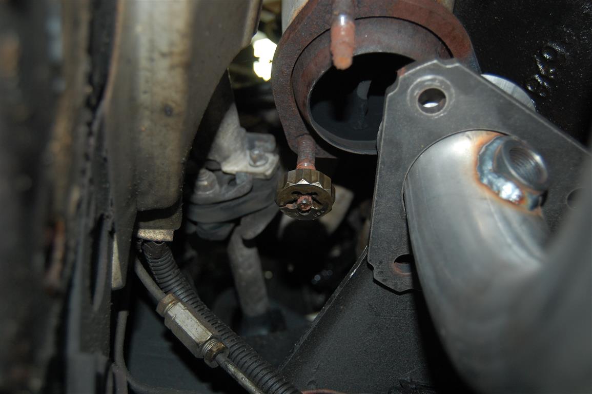
Now some info on the manifold configurations. Except for some special high-performance applications, passenger-side exhaust manifolds came from the factory with a flat surface to provide a seat for the heat riser valve. The heat riser to the passenger side exhaust manifold was also set up for a machined metal-to-metal seal. During engine warm-up, the heat riser assembly stops exhaust gases from exiting the passenger side exhaust manifold. This forces the exhaust gases to circulate through the cylinder head, then to the intake manifold, and finally out the driver-side exhaust manifold. This heated up the engine quicker and allowed correct choke operation. The heat riser valve assembly uses a bi-metal spring that loses tension when heated, thus opening the valve and allowing exhaust flow through both exhaust pipes. Factory exhaust manifolds use 3/8″ diameter studs with 16 threads per inch. These are available from Corvette Central in the correct length for your application. The studs are a crucial component in long-term exhaust flange sealing. As the stud’s threads erode, the nuts become loose, letting the fiber donut seal move around and wear it away.
The first step is to prepare your manifolds for installation. Broken or deteriorated flange studs are often found and can be a daunting challenge to remove for the do-it-yourselfer. I always go there first if all goes well. I then send the manifolds to be surface machined for the best possible leak-free installation. The following photos and captions will walk you through the removal and installation of the studs.
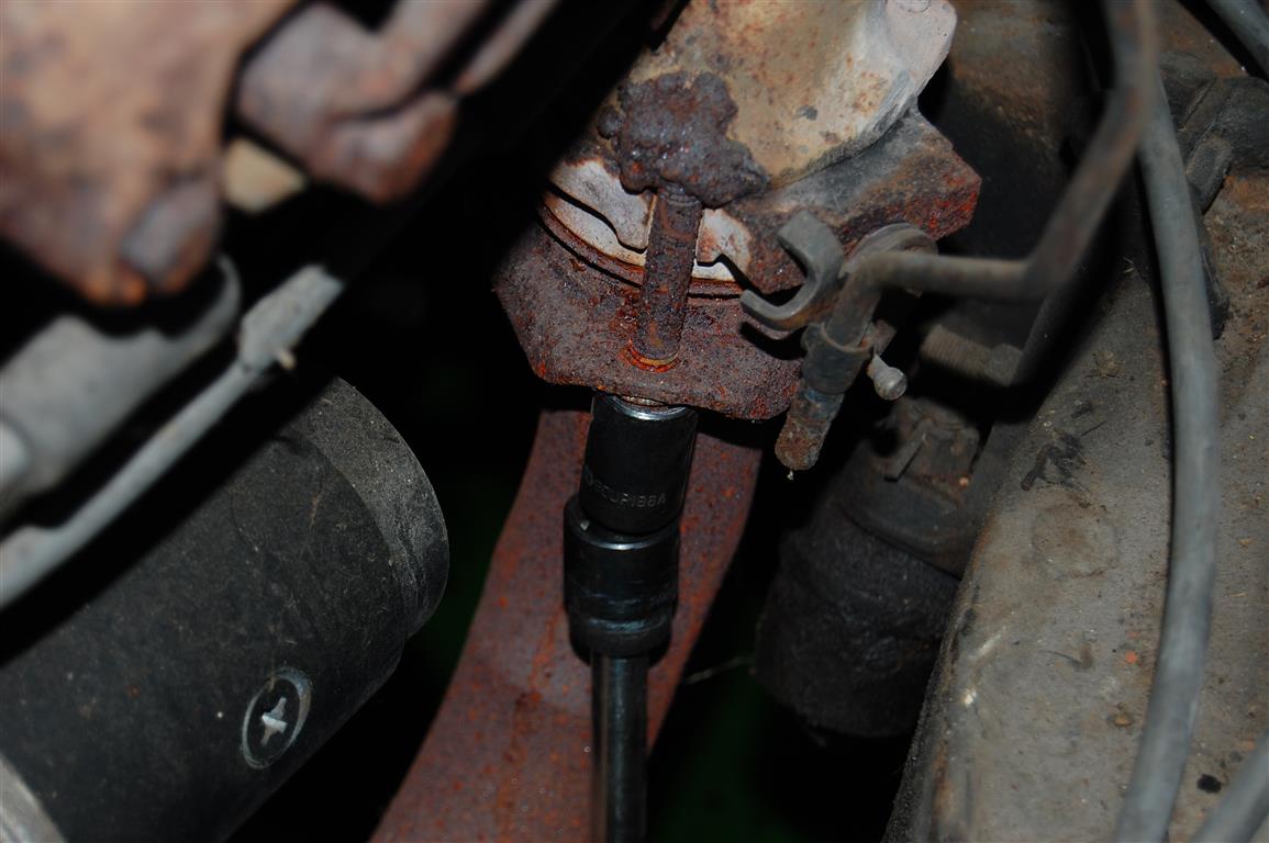
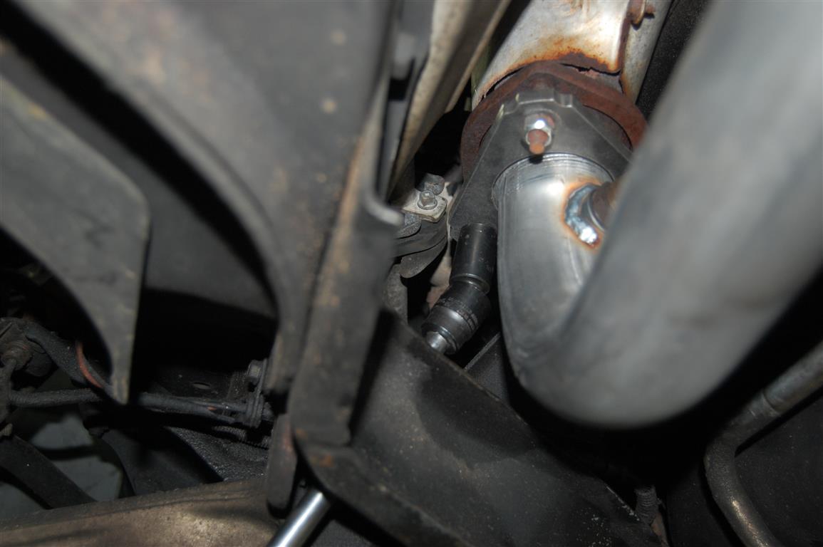
When removing exhaust flange nuts, a good soaking with PB Blaster or Pre-lube 6 brand rust penetrant works exceptionally well at loosening frozen fasteners. Overnight soaking of penetrant works best. Afterward, an air impact wrench set on low can save considerable time and aggravation. Unlike a long bar on a ratchet applying extreme force at one time, the air impact wrench utilizes an internal hammer to slug the nuts loose. Keep in mind: if you use the impact wrench on high, the torque may break the exhaust studs like stick candy. This Mac Tools semi-deep 9/16″ impact socket works well to access the nuts with an extension on the impact wrench. If the air impact wrench will not remove the nuts or you do not have an impact wrench available (air or electric), a propane torch will apply enough heat to help nut removal. Apply heat directly to the nut, avoiding the stud as much as possible. Keep your removal tools handy to loosen the nuts immediately. Watch the fuel hoses and lines when applying heat! Also, watch where you set the hot nuts down after removal!
It is typical to find the exhaust manifold bolt heads corroded away. If you find that a 9/16″ socket is slipping, a 14 mm six-point socket will sometimes grab a corroded or worn bolt. The key is patience, as mentioned earlier. If the nuts are stubborn, do not keep hammering away with the impact wrench or get a longer ratchet. Applying heat only to the nut is very important. If the stud gets red hot, it will twist off. If the nut comes loose but stops, apply more heat until the nut comes off.
A 3/8-16 die should be used to clean the threads before assembly if the studs are in decent shape and do not have severe corrosion. A 1″ twelve-point socket works best to turn the die in the tight confines.

A 3/8-16″ tap is used to clean the threads before inserting new studs. It is a good idea to use cutting oil and patience when tapping the threads. The manifold has gone through many heat cycles, making the cast iron manifold brittle. When using a tap, it can break in an instant and ruin a perfectly good afternoon if it grabs unexpectedly. If the threads are gone, the next step is to use a 3/8-16″ heli-coil insert kit or replace the manifold. The recommended heli-coil drill bit is used to drill out the oversize hole; then, a heli-coil-specific tap is used to thread the hole for the insert.
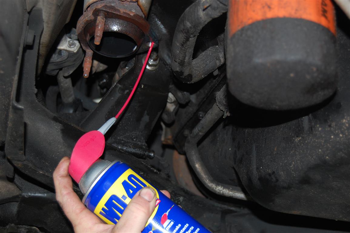
The threads should be cleaned well with WD-40 or your favorite rust penetrant before installing the stud or heli-coil.

The heli-coil insert is threaded into the hole, and the tab is broken off per the instructions. The heli-coil’s twist-in tab breaks off, locking the insert in place. The stud can then be inserted. I use never-seize (or anti-seize as it is sometimes called), coating the threads lightly to aid in future removal.
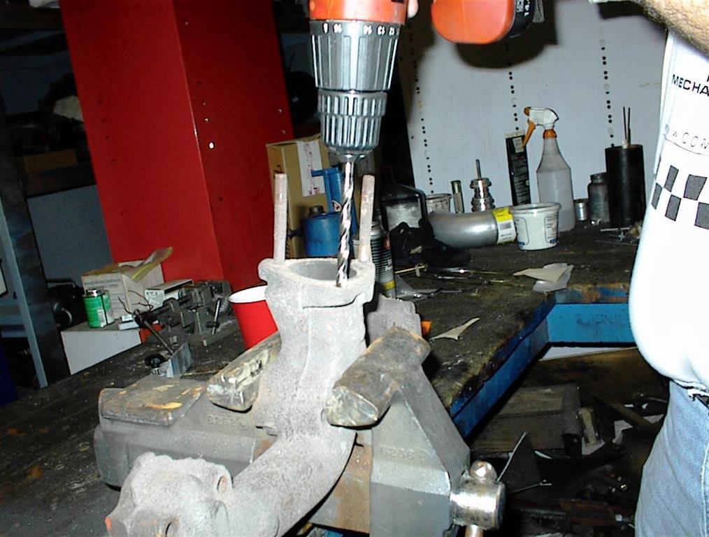
If you have a stud that has broken off, manifold removal is recommended for the best possible drill control during the process. When the stud breaks off flush, it means that corrosion has literally fused the stud and manifold. If the broken piece is not flat, I use a handheld grinder to flatten out the stud. I want the stud to be flat and level with the manifold flange. This allows accurate center punching. Carefully drill completely through the broken piece of stud with a 5/16″ drill bit. If the drill bit is centered carefully, a center punch can break out the remnants of the stud. Tap the threads with a 3/8-16″ tap. The word Easy-out, stud, or bolt removal tool comes to mind, but in a situation like this, they almost always break off, and then things get really messy. Easy-outs work when there is minimal thread resistance, and in an exhaust system, there is no such thing as minimal thread resistance!
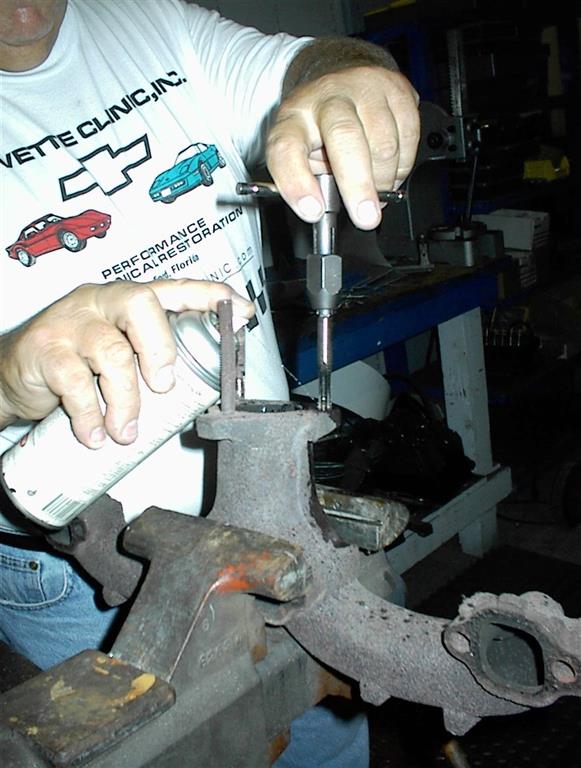
I feel better working on the bench with a thread tap. Here the tap is being doused with rust penetrant as the tap is worked back and forth, slowly cleaning the threads.
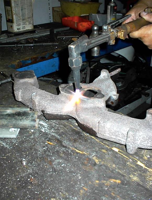
The scaly deposits are removed with heat from the torch. Layers of old gasket and corrosion deposits become dislodged during the heating process. My torch is adjusted with more acetylene to keep the heat lower, which can be determined by the orange glow from the torch. If there were more oxygen present, a bright blue flame would be at work, indicating much higher heat. The scaling occurs when corrosive exhaust gases and condensation seep out the sealing surfaces.

While the torch is heating, a small hammer will work to remove the loose, scaly corroded material. While applying heat to the sealing surfaces, tap lightly with a small hammer to pop off the scaly deposits. This trick really works well in removing the deposits quickly. The scales are extremely hot, and they stick immediately. Long cuff gloves will save a lot of scarring.

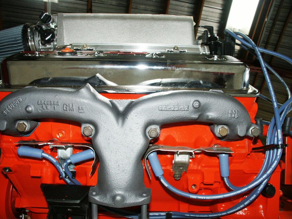
This exhaust manifold has been ceramic coated and has new bolts and washers from Corvette Central, retaining the manifold to the engine. I wanted to use this photo to show how important the plug wire heat shields are. The inside spark plugs are close to the manifold. GM purposely installed the shields to keep the heat off the plug wires. Very often, these shields are tossed because they are in the way, which is not a good thing. Corvette Central has the shields available separately or as a set of four, along with the correct fasteners (which are often required).
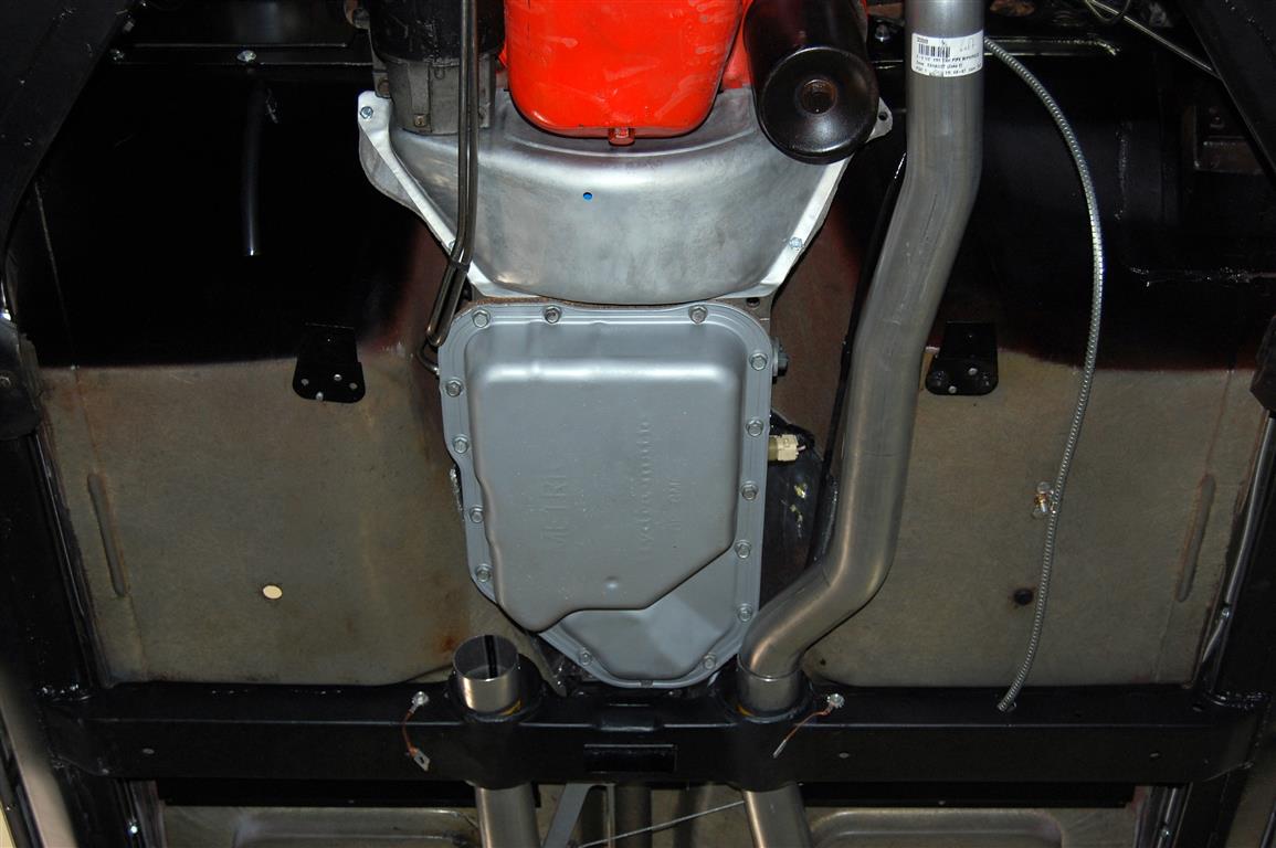
To start with, we are installing a Corvette Central Exhaust kit on a 1965 that originally had a Powerglide automatic transmission. The owner wanted an overdrive automatic transmission so the ’65 could be driven long distances. A 700R4 was chosen because they are a bit easier to install. The rub (no pun intended) comes in where the exhaust goes through the transmission cross member and passes by the transmission pan. Corvette Central had just come out with this really nicely done 2-1/2″ diameter tubing exhaust system for the automatic-equipped Midyear. The thought of trying to stuff 2-1/2″ exhaust into the restricted area was making me concerned, but it worked with a few modifications. Note the smooth flowing bends that the Alpine CNC tube and pipe bender made in the front pipes. Typical exhaust tubing benders wrinkle and dent the tubing during the forming process, which makes this system that much more desirable from a performance standpoint.
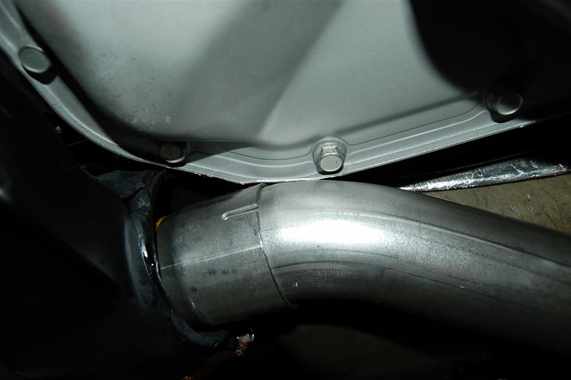
The driver-side pipe would fit, but it was tight against the transmission pan. It also made the pipe very close to the cross member’s opening on one side. This system was originally designed for the Powerglide auto transmission, not the 2004R trans I had installed.
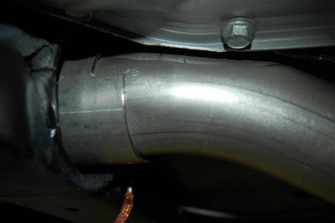
What I was really concerned with was the alternative: bringing the project to the local exhaust shop and having them custom-build a system for me. As it turned out, the pipe would only require a small depression to clear the pan sufficiently. I used my hydraulic press and a piece of steel to make the modification.
The passenger side was also close, but with some juggling around of the pipes, there was sufficient clearance.

Knowing that a 700R4 automatic overdrive transmission would be installed, I tried a 700R4 pan to see how the system would fare with it. The smooth-flowing pipe fits better with the 700R4, requiring no modifications at all. The passenger side was close, but it would work fine with the 700R4 overdrive installation.
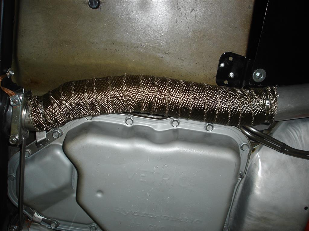
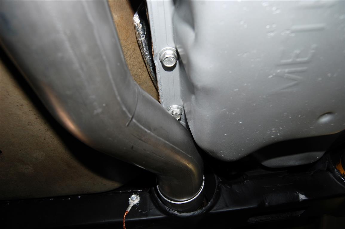
Two very important things should be understood here. The original exhaust system has an exhaust support at the transmission which is often left off when exhaust modifications are made. The reason for the support is to keep the exhaust pipes tight at the manifold flanges, as the engine is rocking around the pipes. The only support the entire system has is at the very end, at the muffler. The supported pipes will prevent exhaust leaks at the flanges and keep the pipes from clanging around in the transmission cross member. The other important issue is the pipe wrap that was installed to keep the floor cooler and keep some heat away from the transmission itself. If we had the factory transmission, we could have used factory shields. The main thing is keeping the pipes shielded in the floor area for comfort. Yes, the pipes will be discolored from the wrap but the aluminized tubing does not corrode badly from being insulated like carbon steel would.
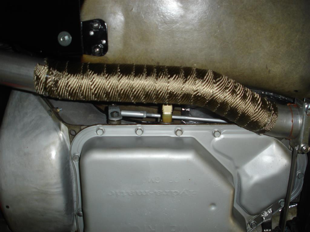
The wrap was applied for the same reason on the driver’s side. It protects the 2004Rs through-case wiring connector and wiring from damage. A similar support was fabricated for the pipe at the back of the transmission pan.
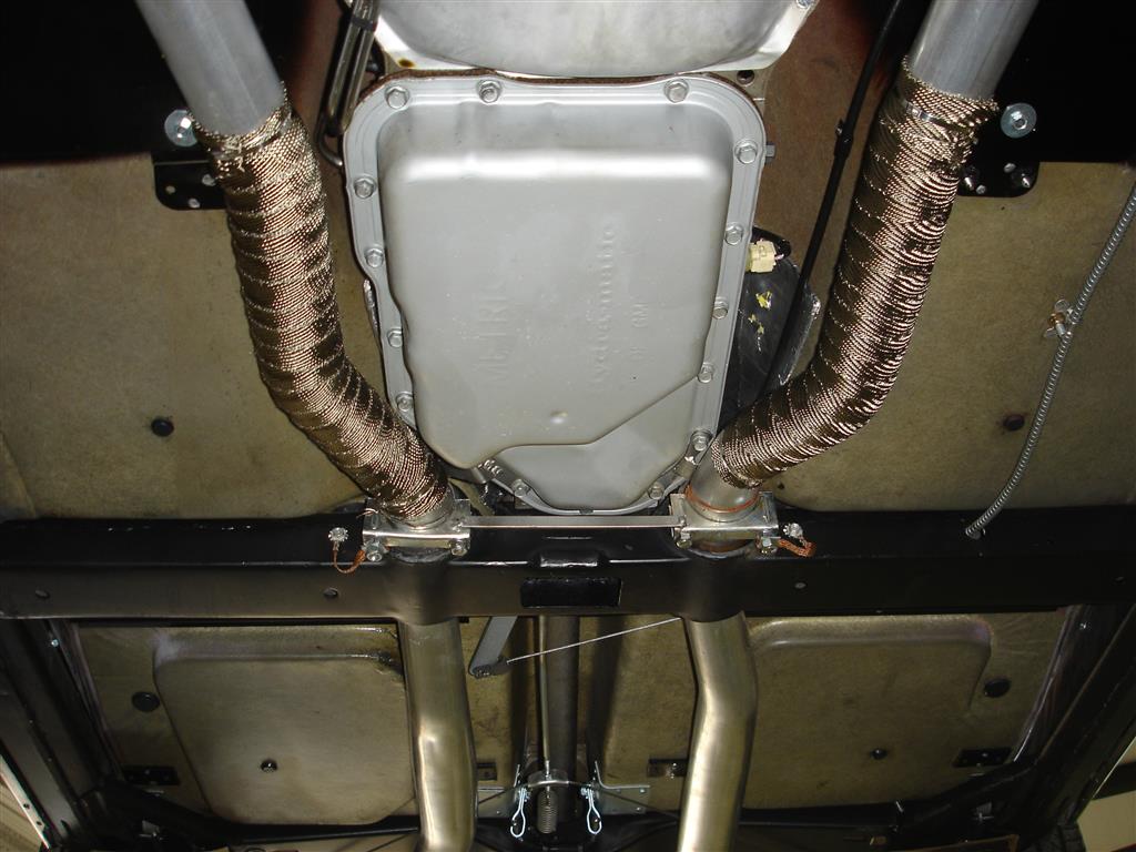
A piece of ½” .125 thick steel was welded from one exhaust clamp to the other To keep the pipe supports from cracking. I installed the ground straps, and the front-end exhaust work was finished. Our next installment will cover the rear pipe and muffler installation along with available mufflers.
Story and photos courtesy Chris Petris
i have a full stock 1978 corvette with L48, 350 CID automatic that was originally equipped with 2″ y-pipe (front and rear, with catalytic converter) exhaust system. This system was replaced with a a CC dual exhaust 2″ exhaust system 5 years ago and I want to remove the dual exhaust (too loud) and go back to the original quieter front and rear Y-pipe exhaust set up.
My question is do I order the front y-pipe with the A.I.R flange or do I order the front y-pipe without the AIR flange. please let me know fast. Thanks
For 78 the proper y-pipe would be part #323740.
https://www.corvettecentral.com/c3-68-82/exhaust/exhaust-pipe-sets/76-79-exhaust-pipe-front-y-75-76-except-air-77-79-323740?returnurl=%2fsearch%3fcurrentsearchcategoryid%3d%26q%3d78%2bfront%2by%2bpipe%26count%3d27
I am installing on my 67 with 327 and 4-speed, the Patriot header exhaust system PN-322145. I have the hangers, but noticed that exhaust donut gaskets were not included. Is this an oversight as I need to procure them, and which size for the Patriot header to the CC 2 inch front pipe.
Thanks, Jim
The patriot headers do not use donut gaskets as they have the rounded flange that seals without them.
I’m thinking about replacing the stock exhaust on my C5 Z06 with an SLP Loudmouth exhaust system? Is it basically a bolt on system or does it need to be welded?
These are bolt-on systems no welding is required.
I’m contemplating replacing my exhaust system on my 92 LT-1 and found the various exhaust system on CC website but it doesn’t show the pipes coming from the manifold just from the Cats can you give me a part number for me to check or some advise?
Thanks
Starting in 1992, the catalytic convertors are connected directly to the exhaust manifolds.
See part number 324239.
The remainder of the system is attached to the rear of the convertors.
Gus Gustafson
Product Assistance
Corvette Central
800 345-4122
Do you sell a set of intermediate pipes for 1981 corvette? If not, am I able to buy just the front section of the item #323100 below?
Here is the front Y-pipe for a 1981. https://https://www.corvettecentral.com/search?CurrentSearchCategoryId=&q=rear+y&Years=1981
If that’s not what you were looking for here are all 1981 Exhaust parts we offer. https://https://www.corvettecentral.com/c3-68-82/exhaust/1981/
Why is the Dual Exhaust system with headers and Magnaflow Mufflers not available for the 63 Corvette?
Due to the exhaust bends needed to fit a 1963, the system would cause a lot of heat around the tool tray/foot well. The 1964-1967 system could work on a 1963 with some modifications but we neither recommend nor advertise it for 1963 because of the heat issue.
Have you ever heard of a heat riser valve stuck or moving erratically? In other words, a valve operating not as designed in a 77 Corvette or in a general C3?
It looks like you have center bolt valve covers in the top picture. If so, those would be mid 80’s heads. I have a set of 86 corvette aluminum heads on my SBC 350, casting number 14101128. I tried to bolt up original ram horn manifolds but ran into fit issues with the top of the ram horn manifold contacting the edge of the valve cover and the lower edge of the head. What manifolds are you using in the above photo?
Do your dual exhaust systems require the installation of the heat riser valve or can it be bolted directly to the manifold on a 1968 4 speed? I am going from headers to manifold exhaust and do not want to put a heat riser in if possible.
Yes, our stock style systems require a heat riser valve or spacer be used.
Thank you for the excellent article. I plan on doing the same conversion. But had heard about the exhaust clearance problem. I plan on using a 2″ exhaust which should help. Also I’m using 700R4. Im thinking of flex connectors maybe 6″ below manifold to allow engine twist before the bend to horizontal. All other Corvette Central components with Magnaflow mufflers. Car is a cruiser and show car. No hot rodding in it’s life these days.
We appreciate your feedback. Good luck with your project!
Do you know where I can get an after market air cleaner for a 1959 corvette 4 barrel.
Here are the 53-62 Air Cleaners we offer.
I’m shipping my Dad’s 1981 corvette to Phoenix AZ. It has been sitting in the garage for 6+ years and hasn’t been started. Please advise on what steps I should take to start the process of getting it back to a drivable condition. Thank you for the input.
A car sitting that long may require major work, just depends on the storage environment and whether any care was provided over the years. The only advice we can give is to take your time and check everything over, from the engine bay to the brakes.
Anyone making a side exhaust for C6?
Unfortunately that’s not something we offer, and not something we’ve seen for a C6.