Is your C4 plagued by body flex when you remove the top? This is a common complaint from most C4 owners. Cornering can feel rather uncomfortable with the top removed since the top provides a substantial amount of rigidity to the chassis. Unkempt roadways also cause problems that will eventually lead to squeaks and rattles.
The top is an integral component that helps to stiffen the chassis. When the top is removed the frame no longer is reinforced because the only frame member is below the doors. The door striker is the only other component that could be considered a source of reinforcement, but being such a small item, the support it offers is negligible.
Unfortunately, this lack of support leads to frame and body flexing which translates to ineffective cornering. It also begins to weaken the chassis as a unit. This became very evident in late 1986 when convertibles were introduced. As a result, all C4 convertibles were equipped with an underbody “X” brace.
Underbody bracing was found to be a simple solution to the frame instability issue. The “X” frame is used to stiffen the frame and body. Coupes benefit greatly from the addition of underbody bracing. This is an easy project for any C4 Corvette owner. Within just a couple of hours, you can enjoy the benefits of a well-supported chassis. Retrofitting the brace is usually simple because late 1986 and newer coupes already have holes in place at the front for the O.E. brace. Although the installation itself is simple, it certainly helps to have a friend assist you, especially if you are using jack stands instead of a lift. It is difficult to hold parts in place and drill by yourself.
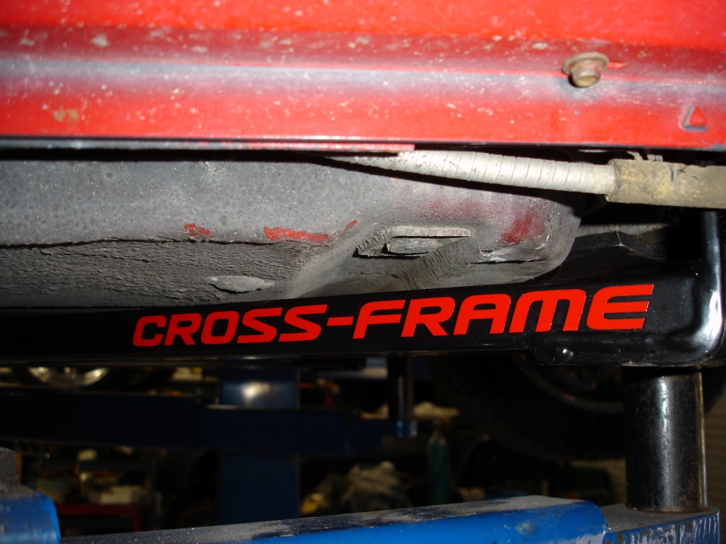
While you may be able to locate a complete convertible “X” frame and necessary hardware, it has become increasingly difficult to find them. Corvette Central offers a cross-frame (part number 184146) built from rectangular tubing that is much stiffer than the O.E. frame stampings. If you ever want to remove the cross-frame it is easy to do because rivet nuts are used to hold the unit in place.
You may opt to install the cross-frame as an assembly as opposed to installing it in individual pieces. If you are using a lift and use jack stands to hold the pieces in place during fitment, this will allow you to check the positioning at all four corners before drilling. As mentioned before, rivet nuts are used to install the cross-frame; once they are in they are in for good, provided that they were not cross-threaded.
To really eliminate as much chassis, frame, and body flexing as possible you can brace the frame area around the upper control arms. The upper control arm frame sections are attacked when your Corvette travels over rough road surfaces. The continual assault eventually changes alignment specifications. Corvette Central offers a camber-brace to strengthen and “box in” the control arm mounting surfaces. This creates a dramatic improvement in handling and prevents flexing. For 1984 L-83 Corvettes, use part number 184129; part number 184113 for L-98 1985-1989 Corvettes; part number 184106 for L-98 1990-1991 Corvettes; part number 184085 for LT-1 and LT-4 1992-1996 Corvettes; part number 184085 for LT-1 and LT-4 Corvettes with electric water pumps; and part number 184138 for 1990-1995 ZR-1 Corvettes.
The camber-brace is another easy-to-install upgrade for your C4 Corvette. You can easily install both the cross-frame and camber-brace on a Saturday and have Sunday available for extensive road testing. Jacking the car up and letting the suspension hang free allows for quick and easy installation of the camber-brace. Wait a few days to allow for suspension settling before having your Corvette aligned. Once you have completed both of these upgrades you are ready to take on rough roads with confidence and you will be pleasantly surprised when you find that alignment adjustments stay intact longer than ever.
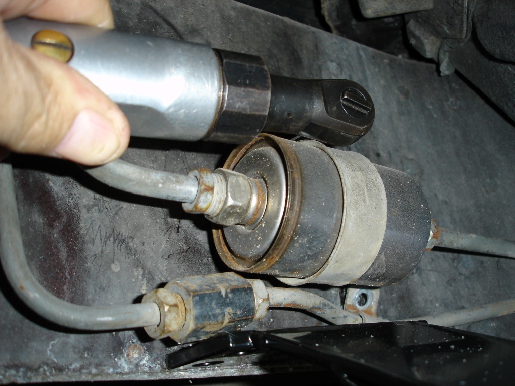
The emergency brake cable retainer is the first thing to remove once you have your Corvette on jack stands at a height high enough to allow for drilling holes. Save the retainer strap for installation later. The fuel filter retainer strap and line clamps should be removed also to allow the fuel filter and lines to be repositioned.
The cross-frame is assembled and set in position at the front frame connector areas. This 1985 Corvette had no provisions for the cross-frame so we have to make all the decisions about positioning. Late 1986 and up Corvettes all have cross-frame mounting points at the front, whether they are convertibles or coupes.
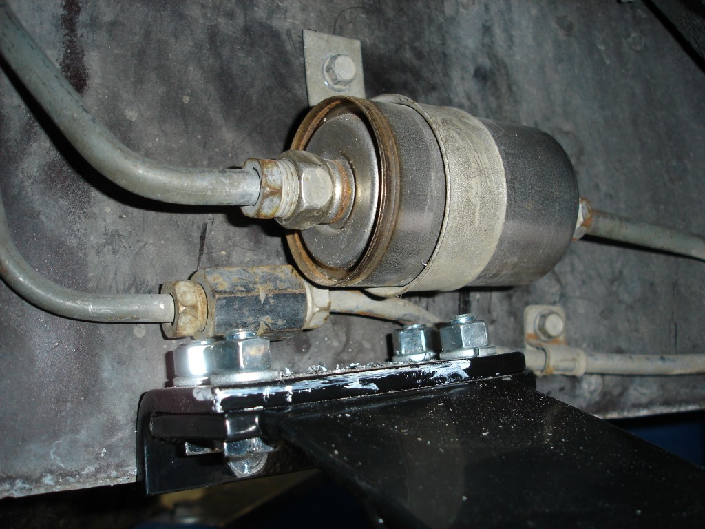
This passenger side frame connector would come in contact with the fuel lines and filter. We remove the 10 millimeter screws holding the fuel line clamps and filter retaining strap to allow for fitment of the frame connector. The filter and a fuel return line are repositioned after the cross-frame is in place.
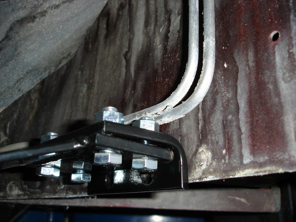
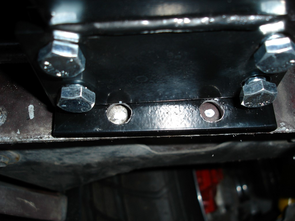
The cross-frame uses frame reinforcement plates on the outside of the frame rails. Careful positioning is extremely important. Once you find a flat position on the frame rail for the plates, look at the position of the outside plate before drilling. Plenty of cross-frame installation “wiggle-room” is available.
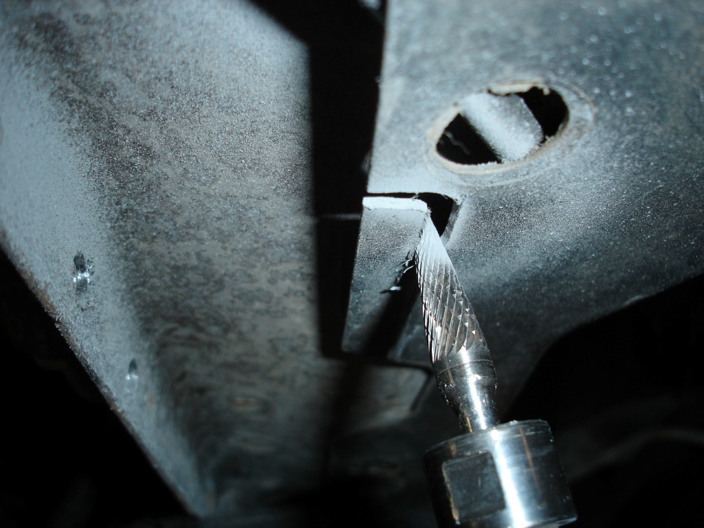
Once we know where the outside plate will sit we have to remove a piece of the offending inner fender so the plate will sit flat. Once the 10 millimeter screws are removed from the lower part of the panel, we wedge the panel down away from the frame with a screwdriver. Then the high speed cutter removes the piece easily without removing the paint from the frame, which would have eventually caused corrosion.
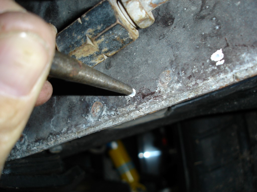
Once the plates are positioned, mark the center with a white paint stick. To get an idea of where the plate will sit in relationship to the frame rib, put the outer plate on the frame and position the inner plate in the same position and then mark the holes.
Use a sharp center punch to mark and make a depression to keep the drill bit in the correct spot. Using a variable speed drill at low speed allows you to come close to the center; however, if you do not center punch the drill bit can still “walk” around. The holes in the plates are larger (allowing some wiggle room) but the best policy is to stay as close to center as possible.
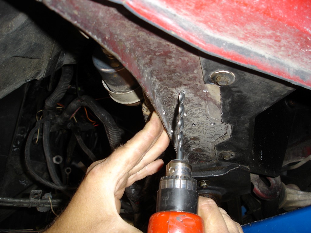
Drilling the frame rib is difficult because of the multitude of spot welds. The metal hardens in the spot weld areas and dulls the drill bit quickly. Dull bits not only make the drilling difficult, they allow the bit to “walk” around and create larger holes than necessary. The drill bit has a tendency to go off center even when the center punch is used around spot welds. HOLD ON TIGHT!
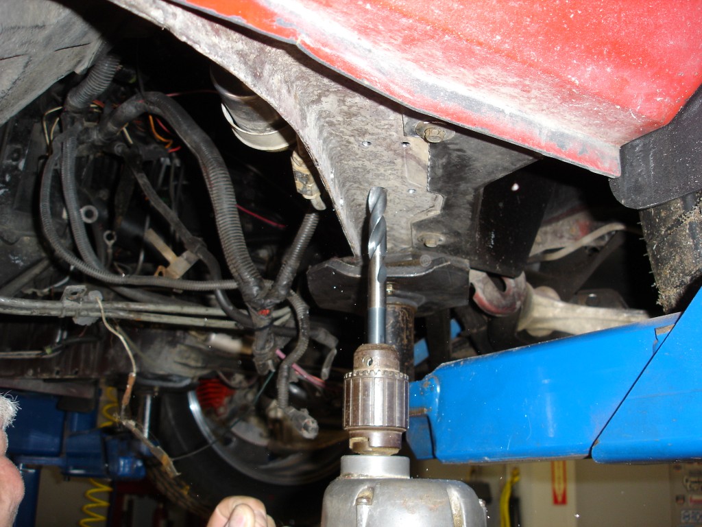
Mark the outer plate holes and drill a pilot hole because of the large drill bit required. When you start to drill the hole, stop when the drill bit just begins to cut the surface. Inspect the mark you made; is it centered? If not, the drill bit can be held at an angle to move it towards the intended spot before it pierces the metal.
Now that you have the pilot hole drilled the 17/32 inch drill bit enlarges the hole for the 3/8 inch rivet nuts. The drill needs to be straight and sharp so the hole is not enlarged more than 17/32 inch. If you were to angle the drill bit now you would make an oversized, oval shaped hole. This is why it is important to drill a pilot hole first.
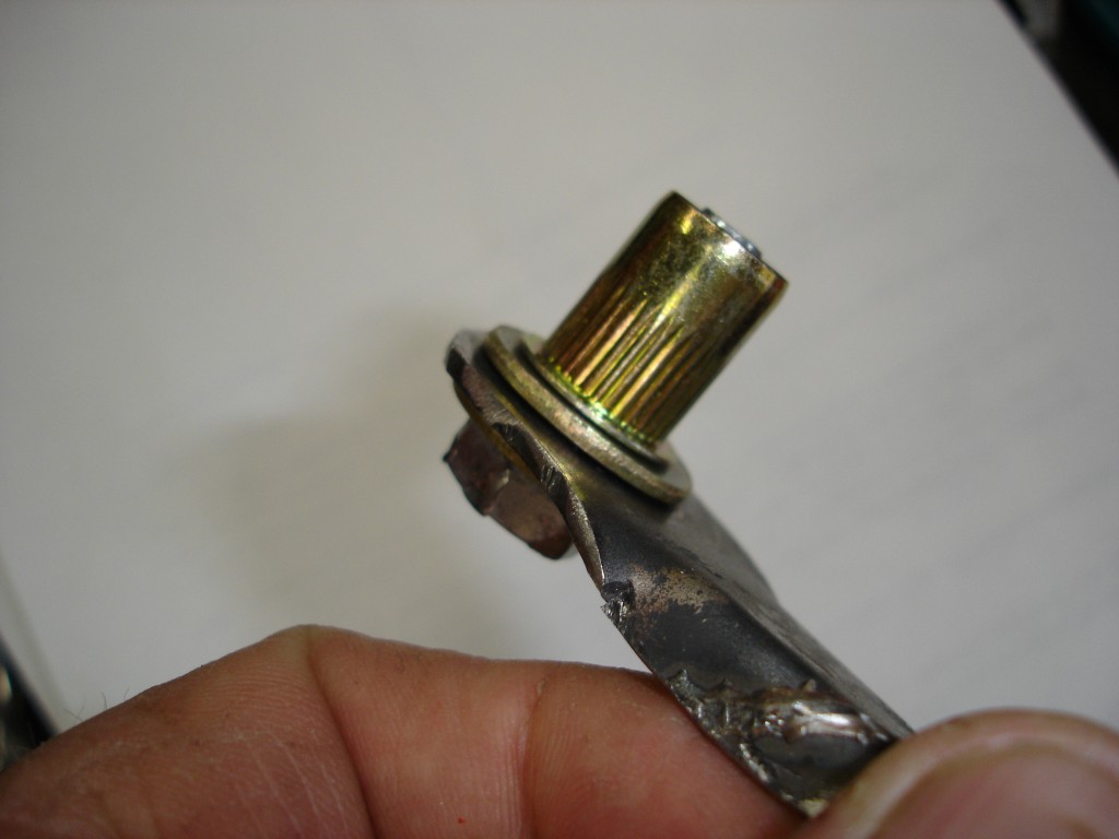
Here the rivet nut is setup on the tool provided to collapse it. Add a SAE 3/8″ grade 8 flat washer between the tool and the rivet nut to keep things centered. There is another SAE 3/8″ grade 8 washer on the bolt side to keep the bolt from digging into the tool. SAE washers fit tighter on the bolt threads and center better than USS washers.
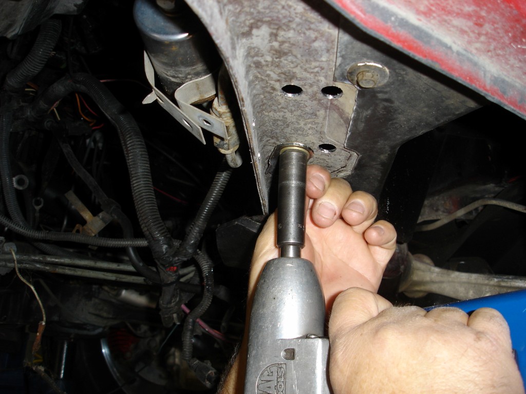
Install the rivet nut and tool in the 17/32″ hole and tighten. As the bolt is tightened the rivet nut captures the metal on both sides creating a permanent, positive retaining mount. The steel 3/8″ rivet nuts provided have a pull-out rating of 12,000 lbs.
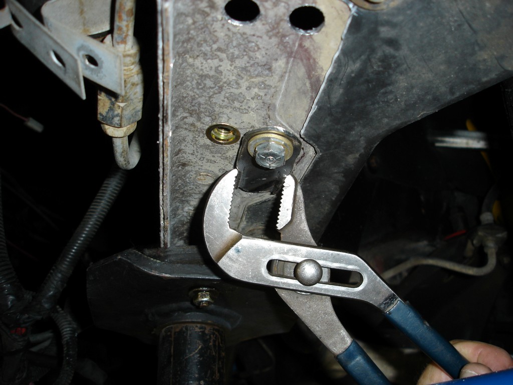
We modified the tool provided by bending an edge to grip on both sides of the tool. The tool rests against the edge of the frame to hold it during tightening and allowed us to grip the tool with pliers when there was no edge available. We considered installing a bolt into a hole that had the rivet nut installed and then let the tool rest against it, but until the rivet nuts are fully compressed they can be damaged or pushed off center.
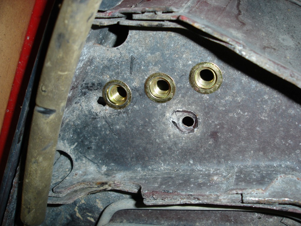
The rivet nuts are in place and will receive the final crimp once the plates are installed and torqued to 45 lbs/ft. The key to proper rivet nut installation is creating the correct sized hole. With a sharp 17/32″ inch drill bit, the rivet nut should only need a light tap with a hammer to insert it in the hole. When the hole is too large, it is hard to keep them centered and flat.
It is best to install the long bolts that go through the inner and outer plates from the inside out. The nut and washer to the left of the photo are incorrect. The plates and bolts get tight with the cross-frame, so the best policy is to assemble all the bolts before tightening anything, which is true with anything with multiple bolts. It prevents cross-threaded mounting holes and bolts.
Drill and place 3 rivet nuts in the rear cross-frame area and you are almost done. By now you are an expert at installing rivet nuts and are probably wondering how you lived without them. The rivet nut tool sits against the frame with no problem here. Watch your fingers! The tool can pinch severely!
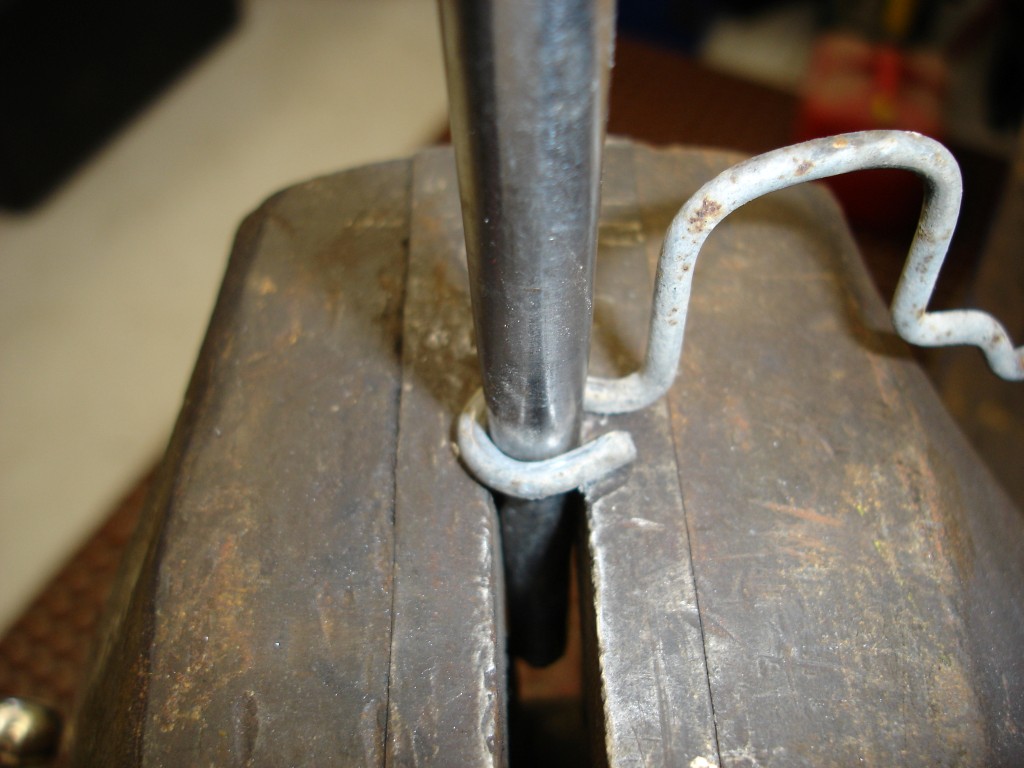
A punch is used to open up the original emergency brake cable retainer. Simply drive it through until a 3/8″ bolt passes through it.
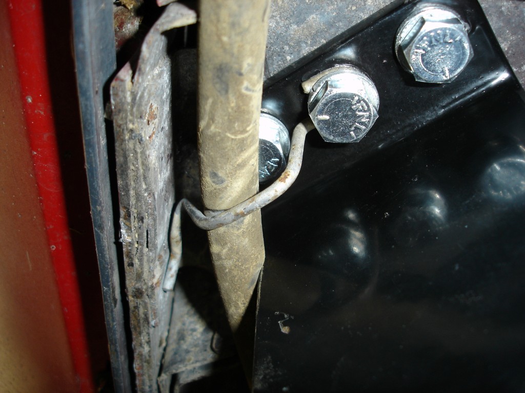
This is the driver side cross-frame mounted with the emergency brake cable retainer modified and in place on the center bolt. A slight bend into the retainer may be necessary to make everything fit, but it worked perfectly.
Once the front plates are mounted solidly, position the fuel filter and lines. The fuel filter retaining strap has a pin to locate it on the frame with a 10mm screw that holds it to the inner frame rail. We were able to move the filter retaining strap up placing the locating pin in the screw hole area. We opened the screw hole up to 3/8″ and then drilled a new hole for the retaining screw.
Camber-Brace
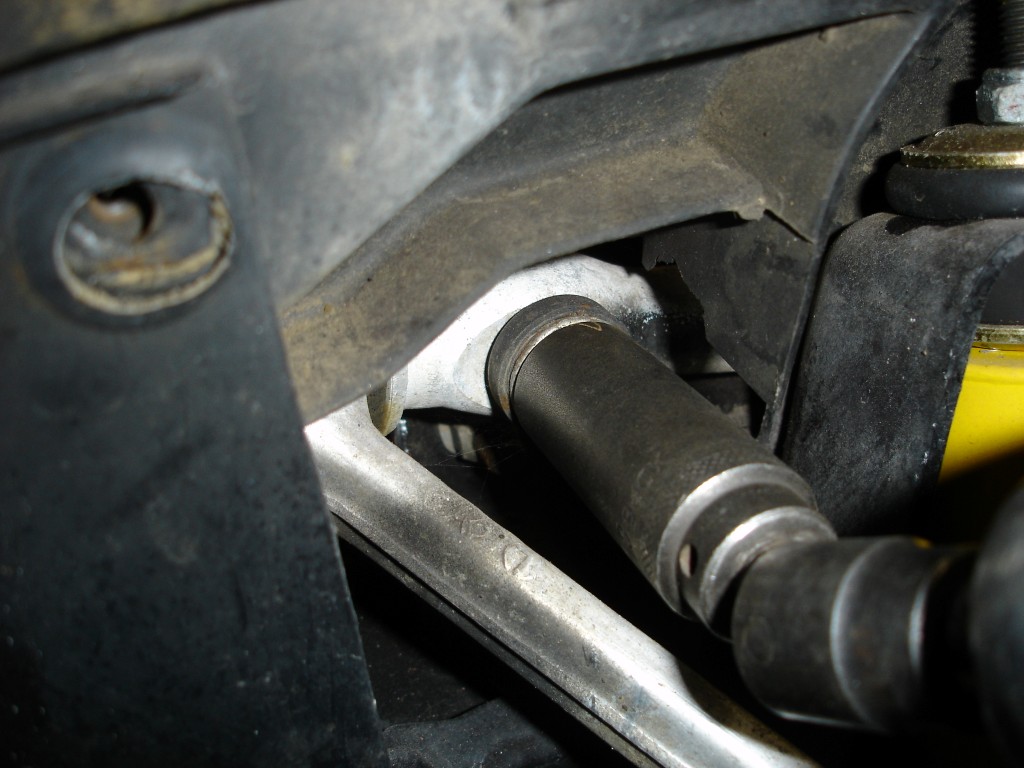
The front control arm shaft to frame nut is removed on both sides to install the Camber-Brace. Check to make sure that the rear nuts are tight so that the control arms will stay in position when the front nuts are removed. The shaft nuts are 18mm self-locking and will require force to remove them until they are almost completely off.
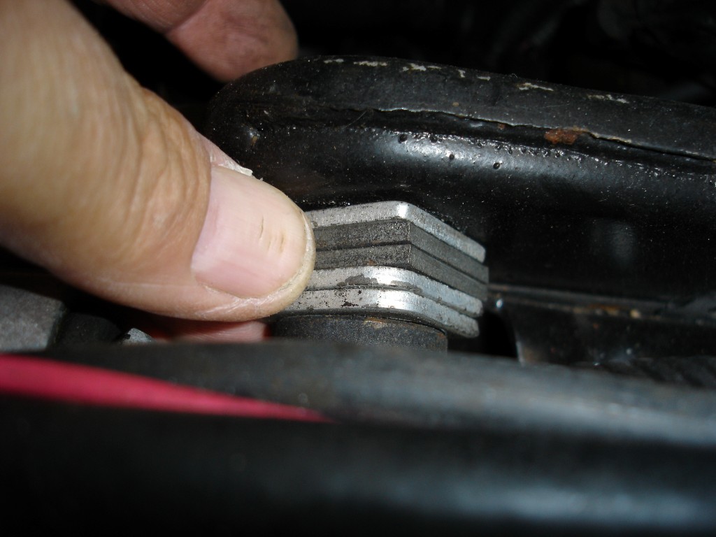
Remember to hold onto the shims when you loosen the shaft nut. Put the shims in a safe place on the same side they were on for installation later. If the rear shaft nuts are tight the rear shims will stay in place.
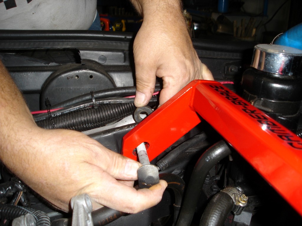
Put the Camber-Brace in position then install the long bolt through the camber-brace and into the control arm shaft. Notice the washer that goes between the control arm shaft and shims. This washer has a cupped side; the cupped side goes towards the control arm shaft.
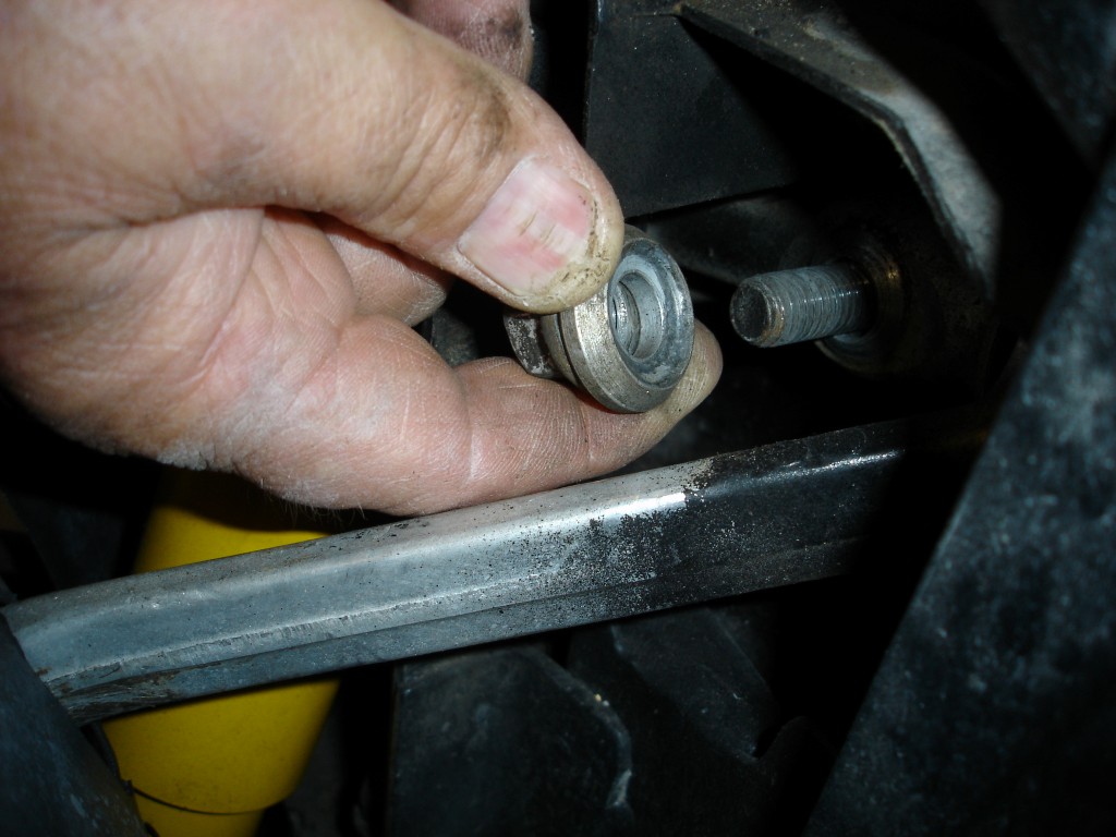
This is the cupped washer on the outside of the control arm shaft. It also must have the cupped side toward the shaft. Once the washers and control arm shaft nut are in place the shims that were previously removed will be installed. Tighten the control arm nut and have the vehicle aligned after a day or two has passed to allow for settling.
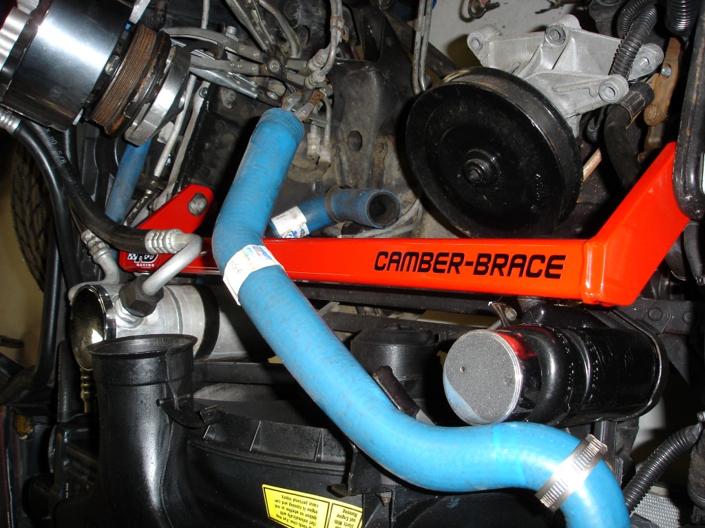
The camber-brace is installed and ready to stabilize the Corvette through some high speed cornering. You do not absolutely have to align the car. If necessary, shims are provided to make the camber-brace fit snugly between the frame horns. We decided to leave the shims out and have the car aligned because I prefer to use the fewest number of shims possible.
Story and photos courtesy Chris Petris





I own a 1989 C4 Convertible. The cork seal on the automatic transmission pan is leaking. The problem is the pan is located above the X brace which I presume was installed at the Bowling Green, KY plant. The question is this:
If removed would a shift in the front and rear frame segments occur causing an impossible realignment of the front and rear X brace to those segments?
The X is installed to stiffen the chassis since there is no roof tying things together.
Assuming the vehicle is in good condition, removing the X to access the transmission will not be a problem.
Regards,
Gus
Corvette Central Product Assistance
Gus,
Thanks so very much.
Regards,
Robert
Can you tell me, if the 3/8″ rivet nuts, washers and bolts you used to secure the chassis x brace would also work to secure the front sway bar brackets for a 1990 corvette? I am looking for a solution that will enable me to move my front sway bar brackets forward to facilitate a coil over modification and provide the necessary clearance on the front end of my C4 Corvette.
I have a 1992 ZR1 and am wondering if the chamber brace will fit. It looks pretty tight compared to a LT1?
It says in the original article that they do have the camber brace for the 90-95 zr1 part #184138
Just came across the cross brace and noticed that it’s temporarily discontinued. Any idea if and when it will be back?
Can you tell me if the Camber Brace will fit on a 1992 ZR1? I would like to add both the X and camber braces if they will fit. If the do, what part numbers should I use?