1968-1982 RESTORATION SERIES
As iconic as they are, 1968-82 Corvettes tend to have issues with their windows, and if they are neglected, major trouble and leakage will probably occur. In short, C3 doors and window glass require periodic service. If it has been more than 10 years since any major work has been performed, restoration is the best plan to assure proper window operation.
Roller and guide wear will occur over time, leaving the glass shaking in the wind and possibly damaging the glass or body. On a positive note, the quality of restoration materials has improved greatly. Today’s weatherstrips are very close to factory fit and density, allowing them to seal the windows correctly. Corvette Central evaluates and provides critical feedback to their vendors, with the result being the best window seals currently on the market.
Door glass must roll up and down consistently in the same position to ensure a good seal. Regardless of weatherstrip quality, glass that is loose and poor fitting will cause leaks.
Tools needed:
Socket wrench and the following sockets:
5/16”
7/16”
3/8”
phillips head screwdriver
drill
1/8” drill bit
It is advisable to strip the window regulator and all related hardware out of the door to clean all the original wax left behind from the lubricant, as the old waxy residue actually slows down window operation. Rust penetrants loosen up the residue quite well. After cleaning, inspect the window regulators and hardware for signs of wear or breakage.
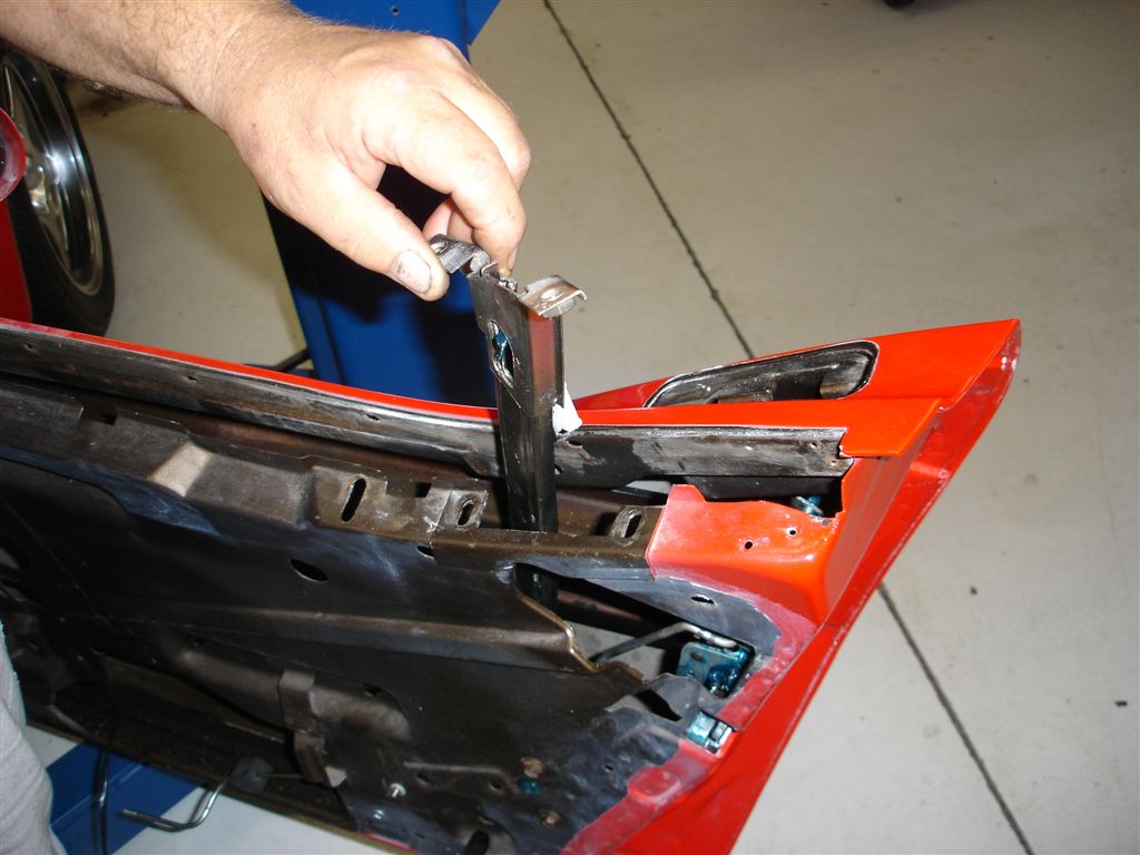
Remove the door glass after loosening the vertical tracks at the top of the door. Also remove the anti-rattle cushions to ease glass removal. Next, remove the upper stop out of the front vertical track. This allows the glass front guide roller to come out of the track. If you have tinted windows, do not let the glass hit the tracks or anti-rattle cushions, as scratching may occur. Tape the top of the tracks and the door itself to provide added protection. Position the glass in order to remove the 7/16” hex nuts that retain the glass to the horizontal track. For additional working space, remove the front vertical guide track upper 7/16” hex head screws including the adjuster plate screws. The glass should now be free to remove from the rear of the door. Next, remove the front guide roller fastened to the glass from the front vertical track. The front roller bearing guide has a stud protruding from the outside of the glass. Exercise caution as the stud can be caught on the outer seal strip during removal.
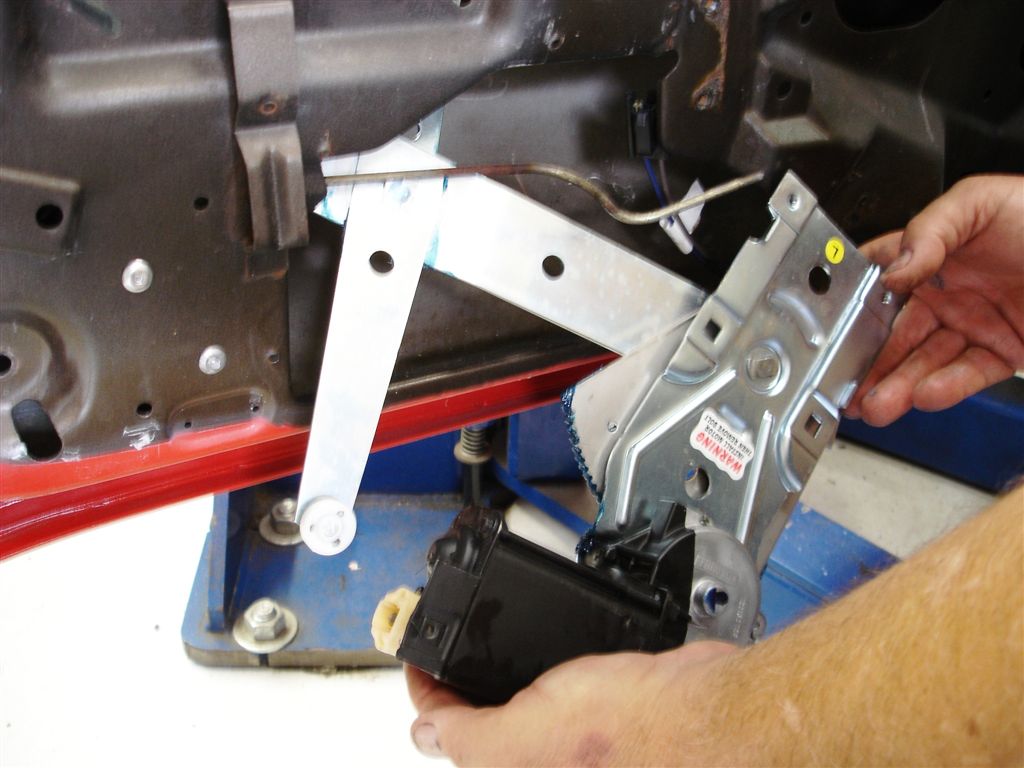
Once the glass is out, remove the horizontal track from the regulator and rear guide roller. The track can be difficult to remove from the rear guide roller. Be careful not to get pinched when the track lets go from the roller. To remove, lower the window regulator to approximately 2” off the bottom of the door. Remove the two 7/16” screws holding the balance track to the door inner panel. The balance track can then be pulled off the regulator roller. Either 3/8” or 7/16” hex head screws hold the regulator to the door (later C3s have rivets holding the regulator in place). Remove the fasteners and then the regulator with the window motor still secured to the regulator.
CAUTION! Exercise care when working around power window regulators, as they have a powerful assist spring to help roll the window up. The power window motor gear rides against the window regulator lift gear. When the motor is removed, the regulator loses control and will force the window upward. This is not a major concern when the regulator is in the car with the window weight applying pressure. The motor can be replaced without fear of uncontrolled movement. After the regulator and attached motor is removed, secure the regulator lift arm to prevent sudden movement. There is a hole provided to put a quarter inch bolt and nut into the lift arm and regulator body to prevent unintended movement. Please exercise caution when performing these steps to avoid potentially serious injury.
Check the window regulator rollers for wear. They should fit tight on their support shaft with no perceptible play. There are three rollers affixed to the window regulator: two are located in the horizontal lift track and the third is in a horizontal tilt adjustment track. Loose window regulator rollers in either track allow the glass to tilt.
When window lift motor gear wear occurs, the door glass will no longer reach the top of its travel. Listen for drive gear slippage on the window regulator gear. The window motor’s reduction gear is spring loaded to reduce force during travel. This prevents the window from slamming into the end of its travel. Replace with Corvette Central’s power window motor gear (part #283002).
There are two guide bearings to keep the glass in position (fore and aft) while controlling tilt. One is attached at the front of the glass. Another bearing with a square guide and roller assembly rides in the horizontal and rear vertical track. Worn guide or lift rollers make it impossible to keep the window adjusted correctly. These roller or bearings are commonly worn and loose. Severely worn guide rollers/bearings can also cause your paint to be damaged or possibly break your glass when it crashes into the pillar post. Part #283067 would replace the front glass guide roller/bearing. The rear guide roller/bearing is part #283068.
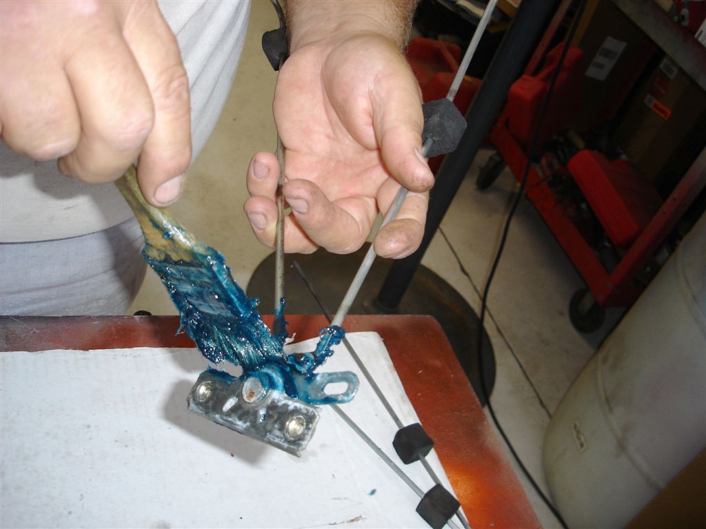
Once the window guides, gears, rollers and affiliated parts are removed, the door latch/lock assembly can be removed for cleaning. Similar to the window regulator, the door latches get sticky from the wax base left behind. Let the latch soak in a pan of mineral spirits to loosen up the gunk. Once the latch is clean, lube it well with synthetic chassis grease. It is recommended to replace all the latch linkage clips while everything is apart.
Before adjusting, reassemble all of the removed items.
Adjustments
When positioning door glass, it is best to make small incremental adjustments. Never slam the door before checking for door to glass interference. Compromise is the key when you are sealing any movable glass. In some cases, once the window has been adjusted in the best possible position, the weatherstrip must be shimmed to fit. There is no exact science to installing or fitting weatherstripping. It may be helpful to take digital photos of the original weatherstrip before it is removed.
Door Panel Removal 1968-1977
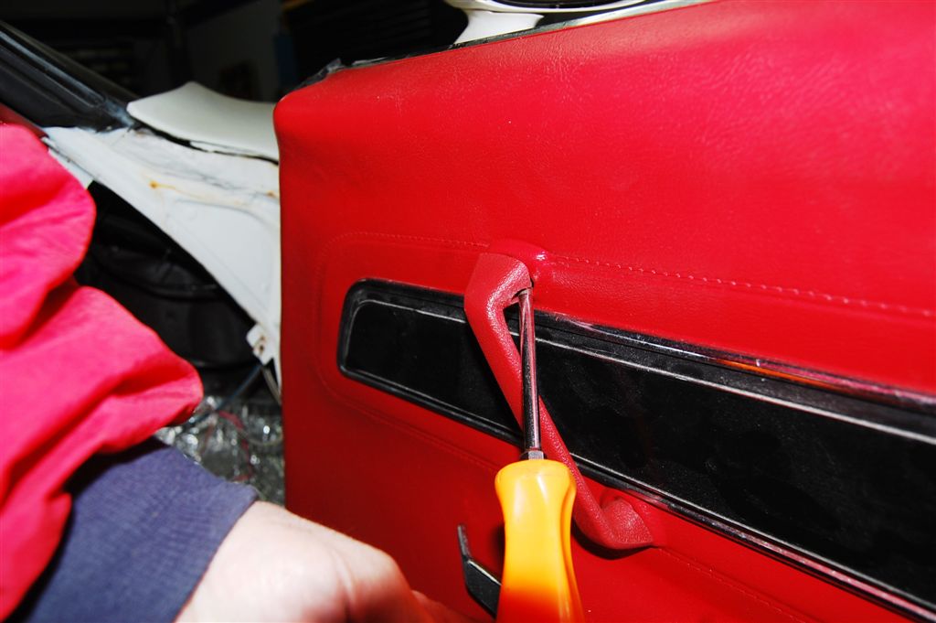
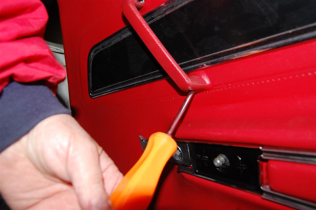
These door pull handles were not used on the 68 door panel (it was incorporated into the panel itself). Pay attention to the angle that the screw goes in to avoid damaging the threads during installation.
Both the upper and lower screws are 10-24 machine thread. Very common to find these screw threads damaged. Running a 10-24 tap through them is a good idea.
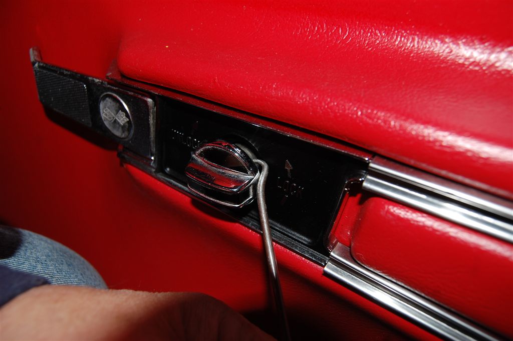
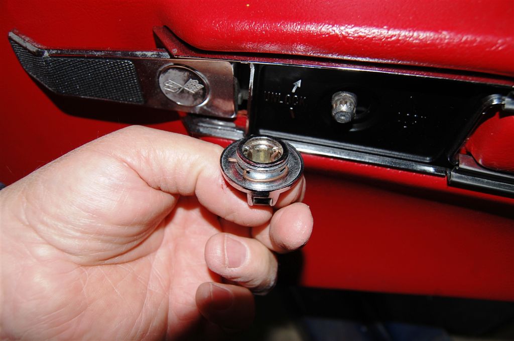
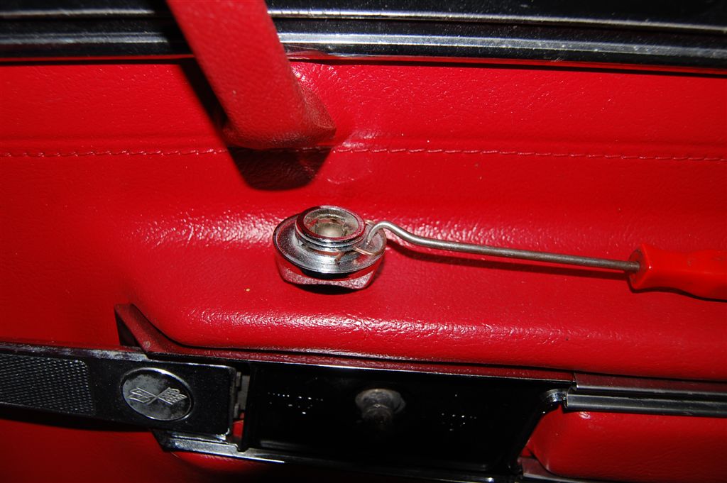
The door lock knob has a spring clip to keep it in place. We use a curved, pick like tool to pull it off. In this case, it was easy an clip to remove, as the plastic washer that is used to prevent metal to metal contact was missing.
IMPORTANT: the door lock knob has a flat spot with missing splines to assure correct positioning. This position assurance device can be damaged with a hammer. Make sure the flat spot lines up with the door lock mechanism.
This should give you a good idea what has to be done to remove the lock knob clip.
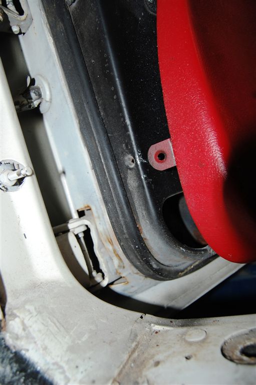
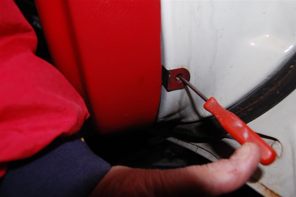
The panel has a clip with a screw that goes into the outer perimeter of the door. Check to see if the screw hole is stripped so that it can be repaired before you install the door panel. Using a piece of .035 metal plate, drill a 1/8” hole. Epoxy it on the inside of the door so the screw will hold tightly.
Same clip at the rear of the door.
You do not have to remove the door release handle to remove or install the door panel. Reach in and pull the handle out with a couple of fingers and then pull the panel over it. You will have to lift the top of the panel over the ridge at the top of the door before removing or installing it.
Door Panel Removal 1978-1982
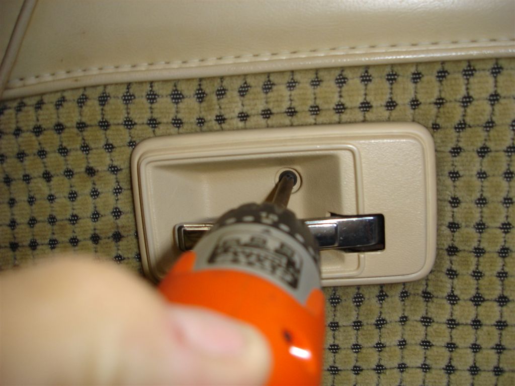
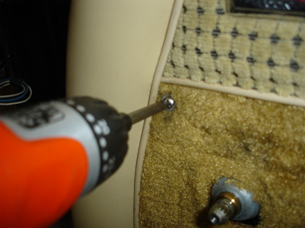
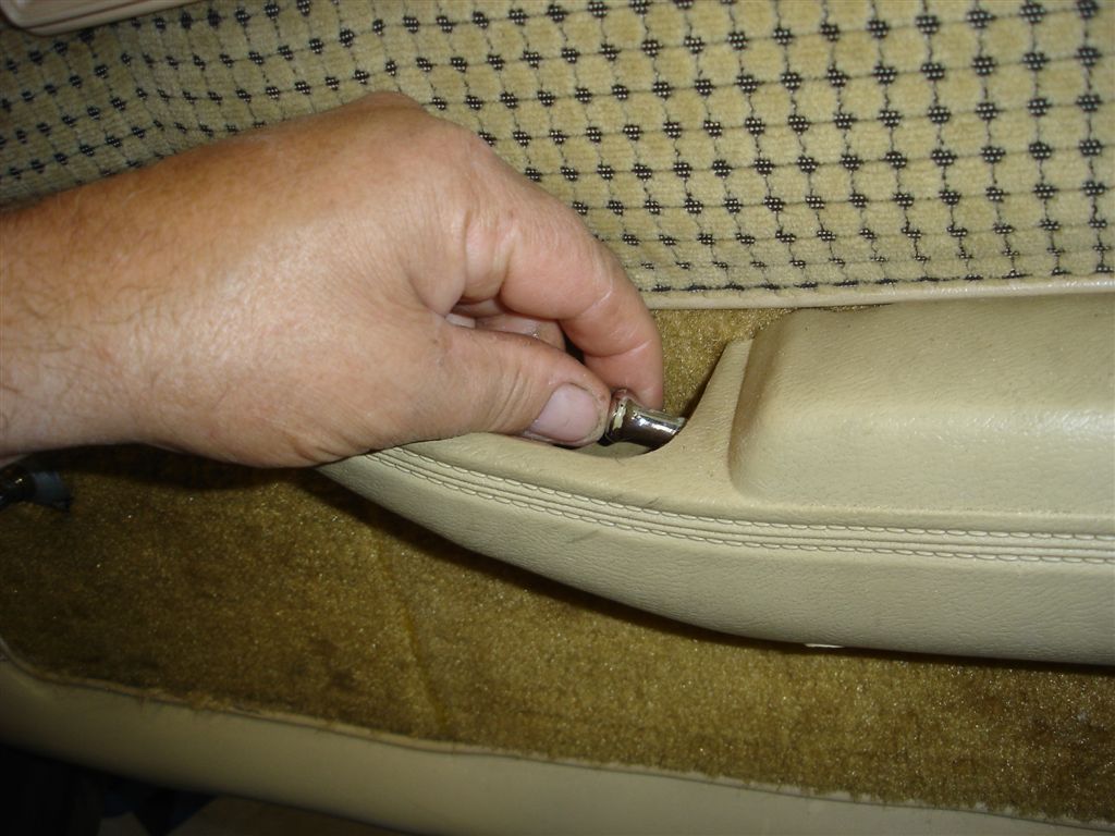
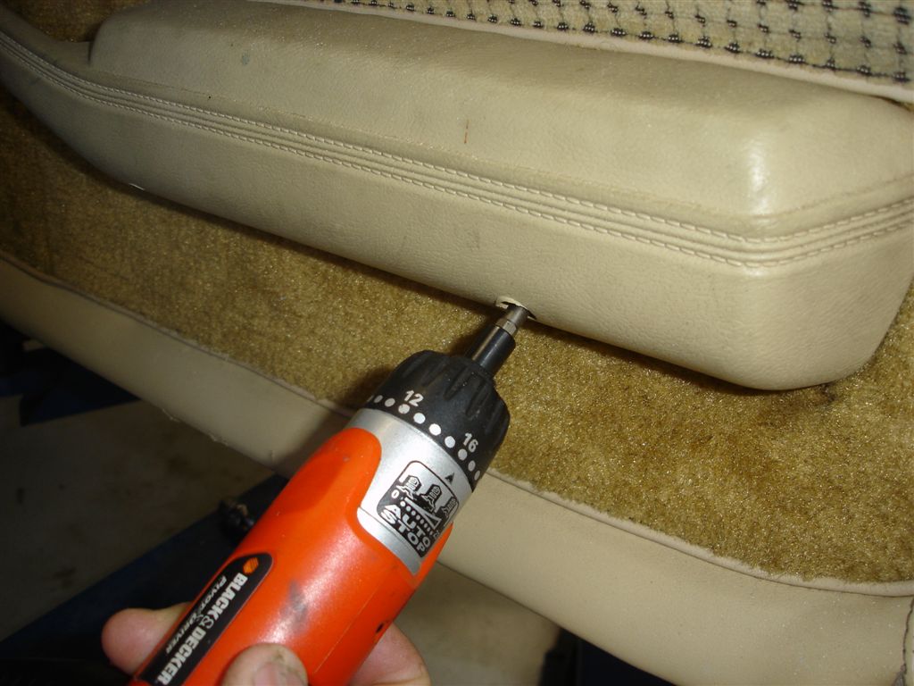
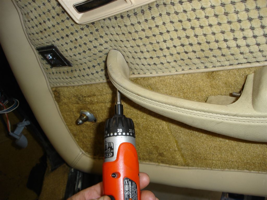
Remove the door handle bezel phillips head screw.
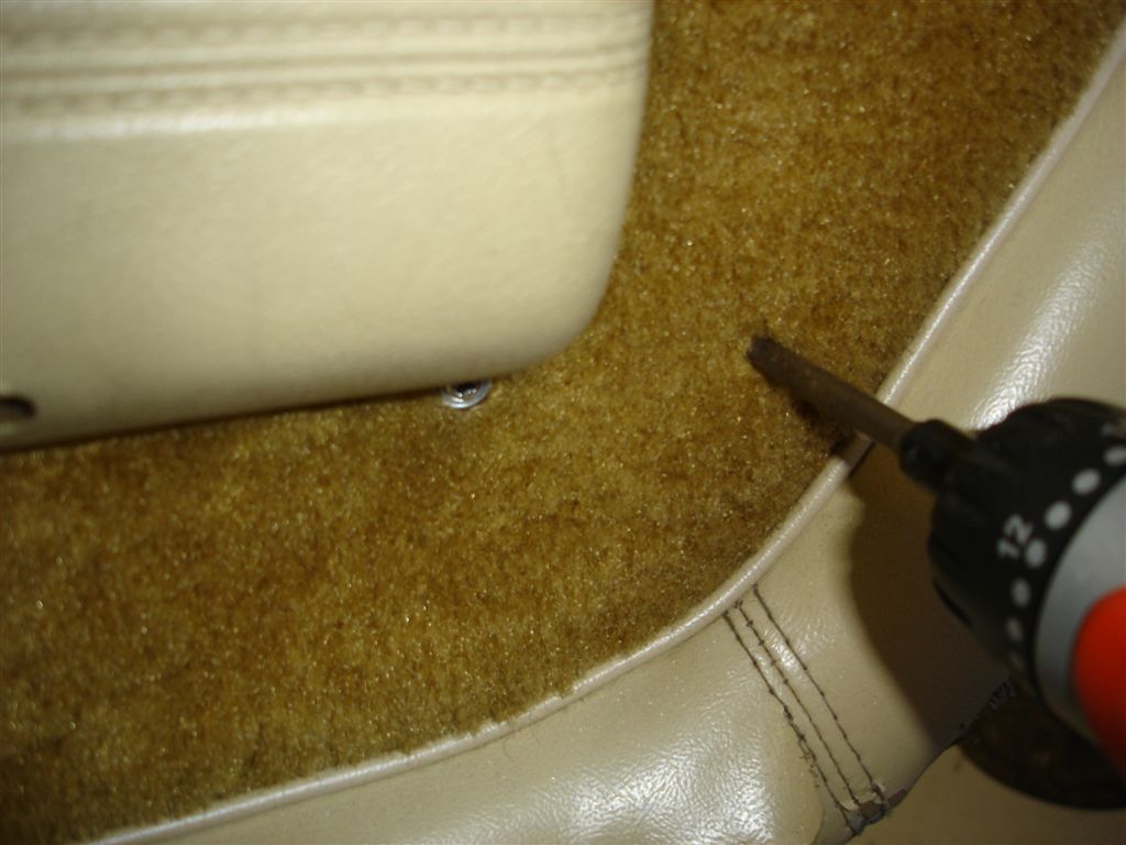
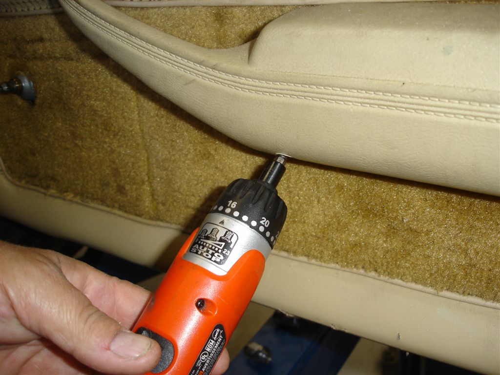
Another phillips head screw buried in the lower part of the door panel.
This phillips head screw can be hard to see. The door panel tugs on it.
Unscrew the door lock knob counterclockwise.
Before you remove these screws, try tightening them first. If the screw holes are stripped you can use a J-clip on the door to get them tight.
Make sure the screw will hold tight.
This screw should be shorter than the middle and rear screws. If the screw is too long, it can interfere with the window regulator.
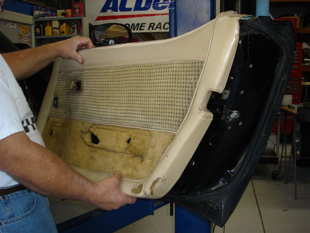
Pull the panel out at the bottom, then lift up to release it from the upper vertical rail it sits on.
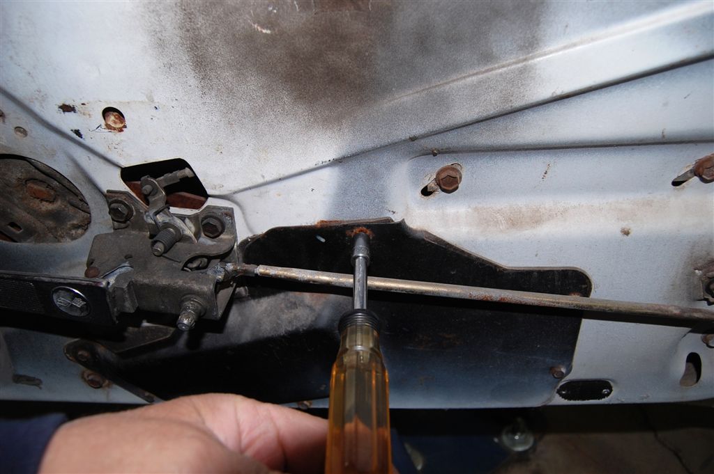
The 5/16” hex head screws retaining the lower access panel should be removed next. 1978-82 cars will have an additional 7/16” hex head screw in the panel to reinforce the power window motor. The panels do help keep noise out and seal the vapor barrier sheet.
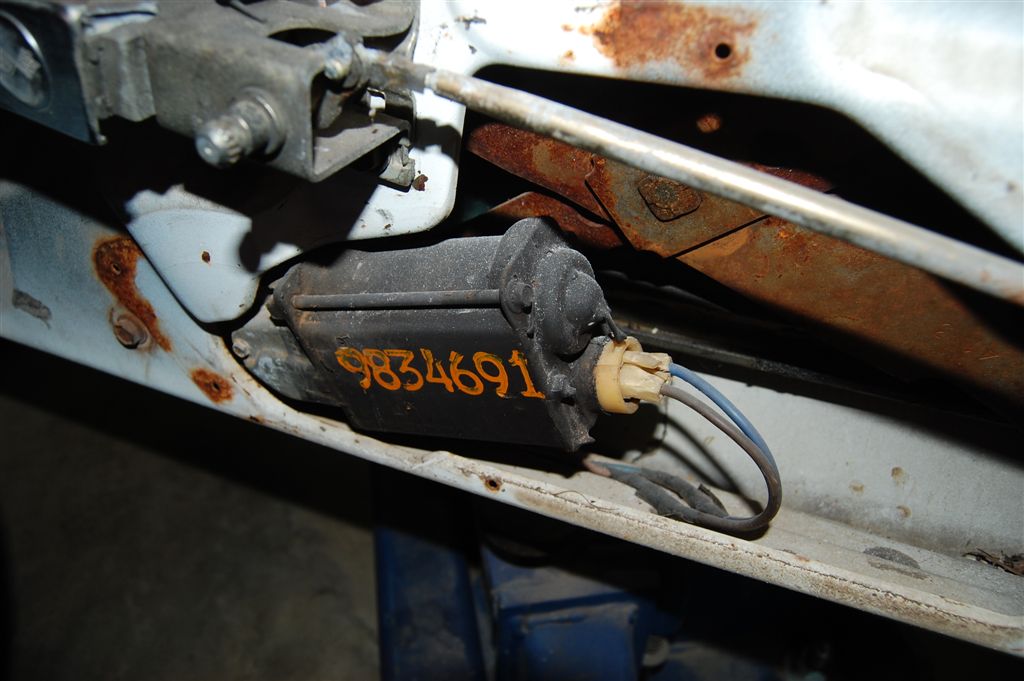
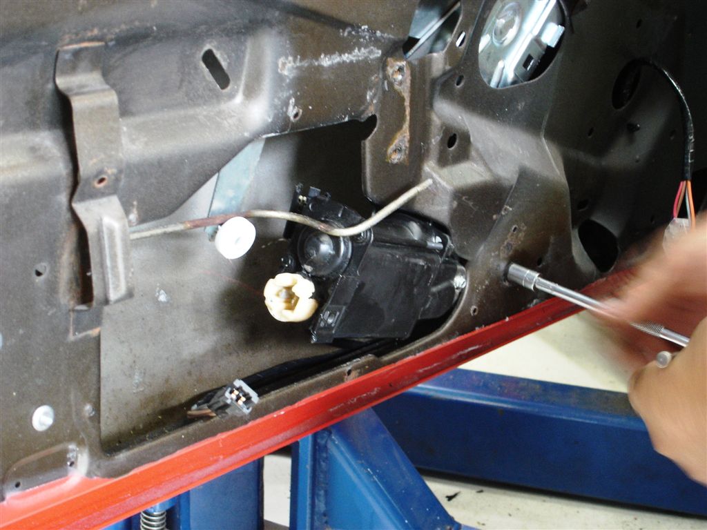
This 1977 has an original window motor and some questionable wiring. Both of the high amp wires were spliced and taped for some reason. It is possible to replace just the motor by reaching on the inside of the regulator and removing the 7/16” screws that retain the motor to the regulator. It helps to remove the lower 7/16” screw holding the regulator to the door so the motor has enough area for removal.
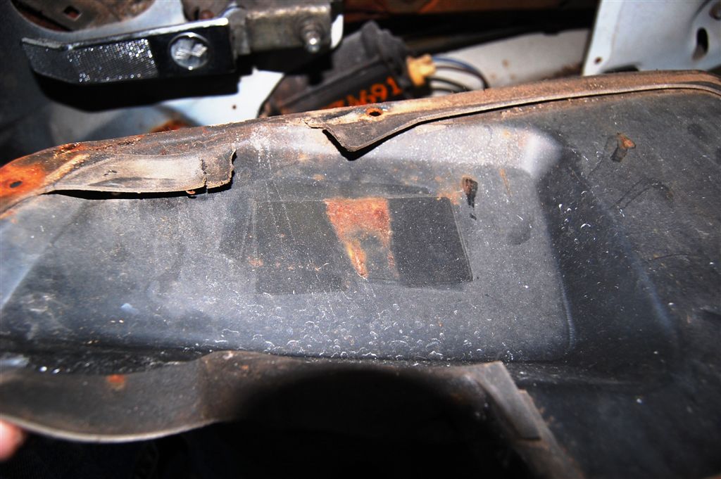
Witness marks from the motor bumping and rubbing against the access panel are evident.
Note the rectangular square with the rust streak in the middle of the access panel. An anti-rattle cushion is used on 1968-77 cars to keep the motor from hammering on the access panel. Although the cushion will prevent the rattle, it does nothing to prevent the breaking of the lower regulator tab. The motor is flapping in the breeze without the reinforcement. We suggest making an L-bracket to attach to the motor frame screw. Then a hole for a 1/4-20 screw can be drilled in the access panel to attach to the bracket.
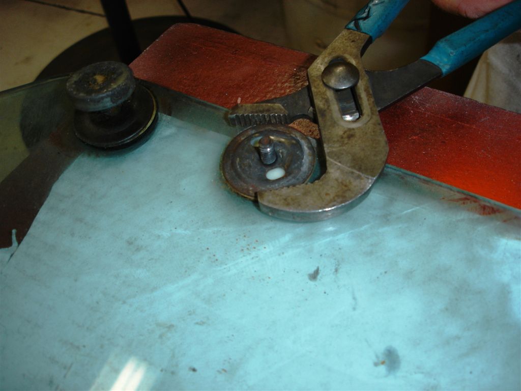
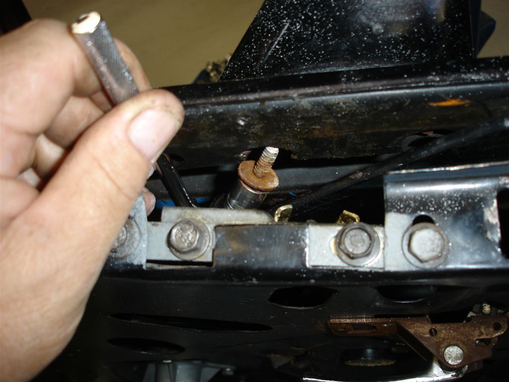
This is one way to remove the stubborn, through-the-glass studs and front guide roller bearing. Take extra caution to prevent cracking of the glass. Corvette Central part #283035 makes this job easier. Used on 1969L-82 door glass, it takes some of the fear out of removing the special nut. Make sure the through-the-glass studs are tight before putting the window back in.
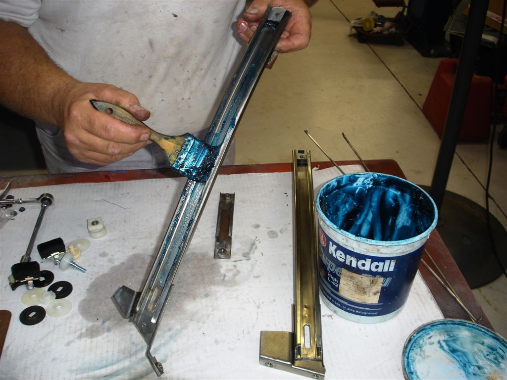
Begin assembly after applying a coat of chassis grease to all the tracks.
Install the vertical tracks now before the door outer seal strips are installed. The rear guide roller bearing assembly has already been installed into the rear track.
The window regulator and motor are installed as an assembly. We are using part #283151L stainless steel regulator for long, trouble-free operation. A new motor was in order so we used an item #283092L new motor. The L suffix denotes left door.
These new regulators have provisions for 1/4-20 bolts for retention. Many of the replacements require welding nuts to the regulator. GM used rivets on 1980-82 cars and they were always loose. The bolts are preferred over the rivets, as they keep the door in good shape.
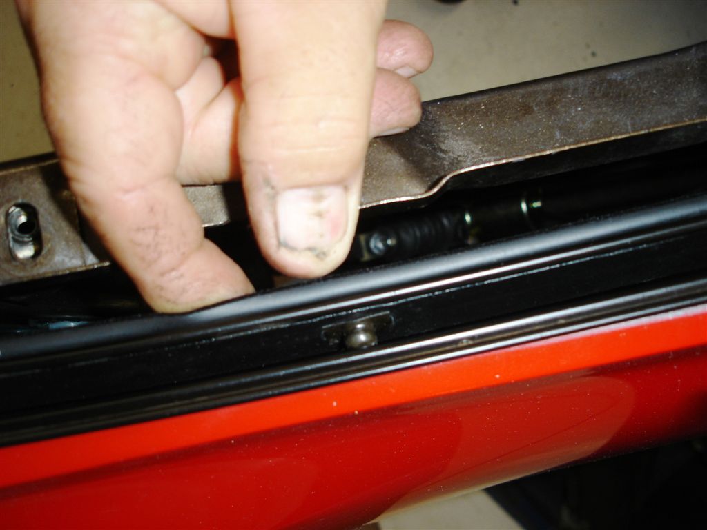
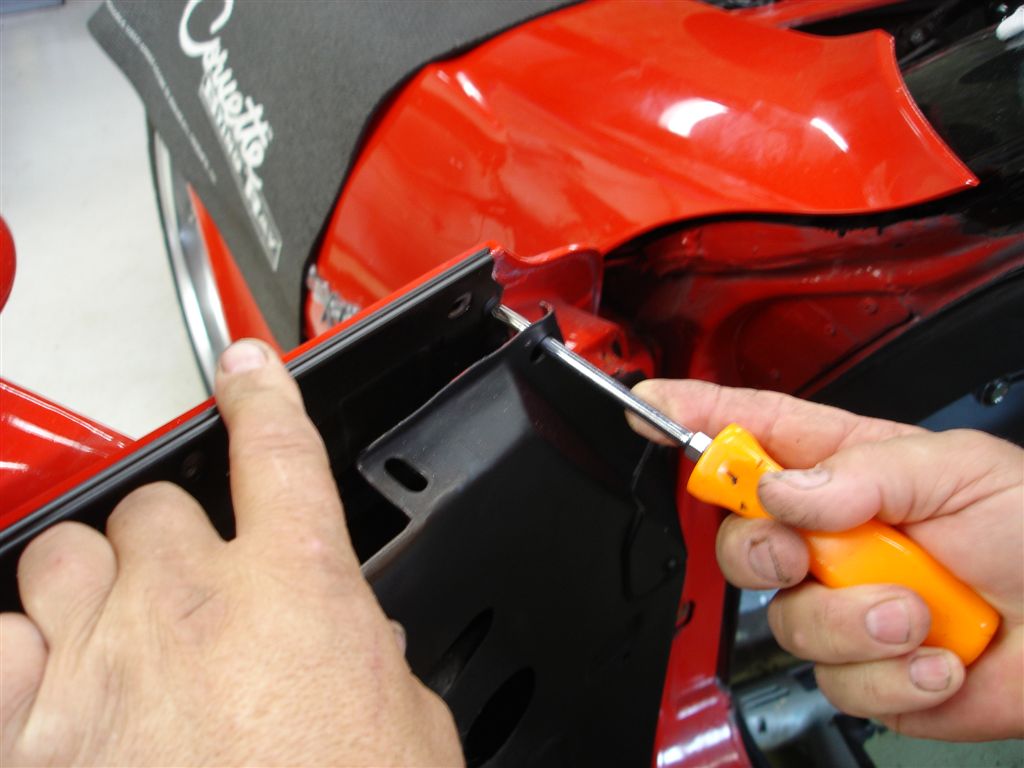
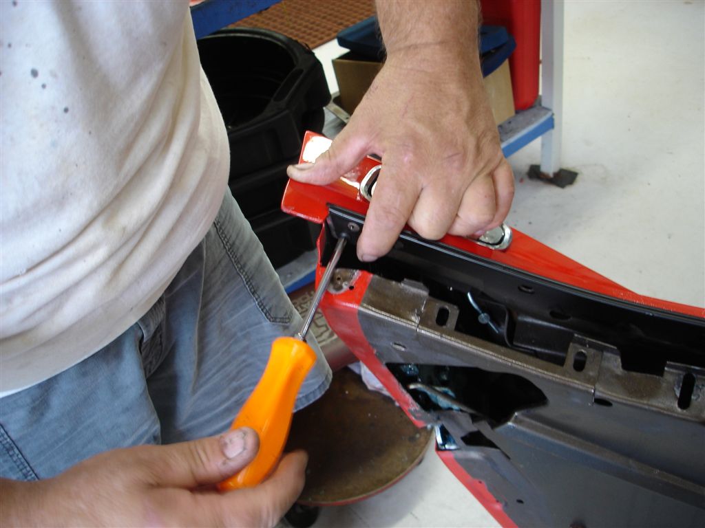
Before we go any further with glass installation, we need to install the outer seal strip and stainless trim. This ‘79 had an early replacement outside seal strip (a rubber blade that never worked well). Originally, they were the only replacements available. Today, Corvette Central has the correct replacements with proper flocked material, correct beading and fit. The strips have pop-in retainers with two phillips head screws (front and rear) to hold them in place.
Here we have the proper outside seal strip being installed. These strips are an integral part of window sealing. They should fit close to the glass to keep water out of the door. The strips also keep tension on the glass to prevent rattling on the outside. It is much easier to replace these seals with the glass out of the way. If the stops are removed, they can be replaced with the glass in place (let the glass down as low as it will go). As we proceed, we’ll cover where the lower stops are located.
These are the screws that hold the stainless trim to the door before the outside seal strips are installed. Apply wax under the trim to prevent corrosion. This is the right way to paint your car (no paint line where the trim meets the door).
Another phillips head screw at the rear for the stainless trim. We painted our project car stainless trim black.
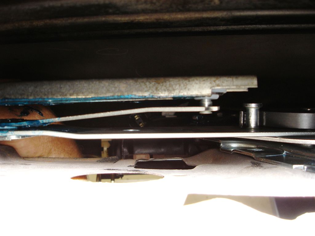
The horizontal track to which the door glass connects is installed. Pushing the track on to the rollers can be difficult (watch your fingers). Front roller shown. The rear roller is slightly more difficult to secure. Wiggle the track while pushing on it.
Once the door glass track is in place, the small horizontal track that controls glass front-rear tilt is installed. We usually try to put the screws back at their witness marks from the previous adjustment. If there are multiple witness marks, we start in the middle of the adjustment.
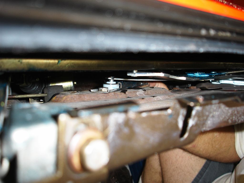
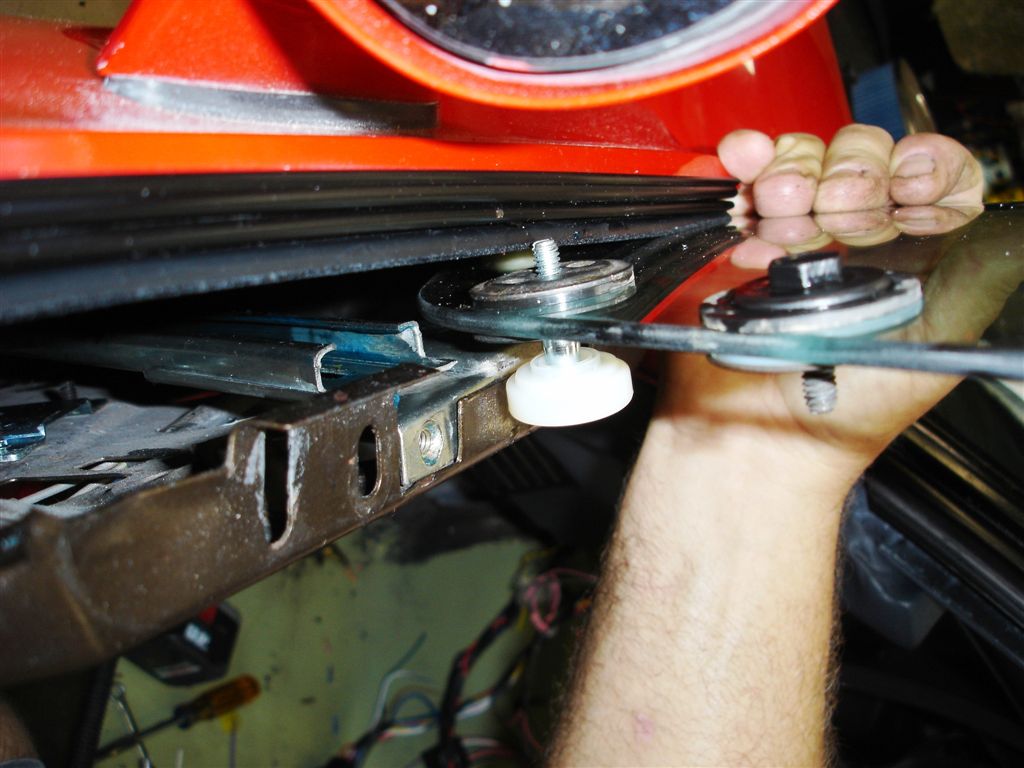
The glass can be now installed, starting with the front roller bearing. Exercise caution as the protruding stud of the front roller bearing can catch on the seal strip and tear it.
Carefully lower the glass into position. The front vertical track is left loose in the door to allow it to get as far away as possible.
Watch the front glass-to-track stud as it goes past the outside seal strip. It gets tight between the seal strip and door opening on the inside.
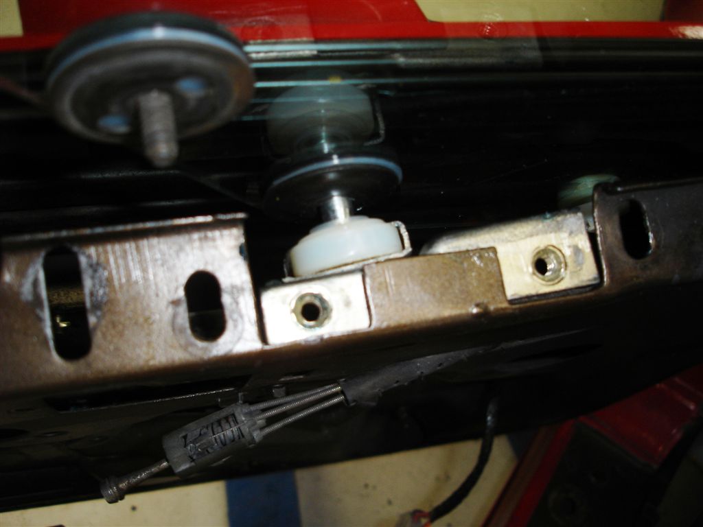
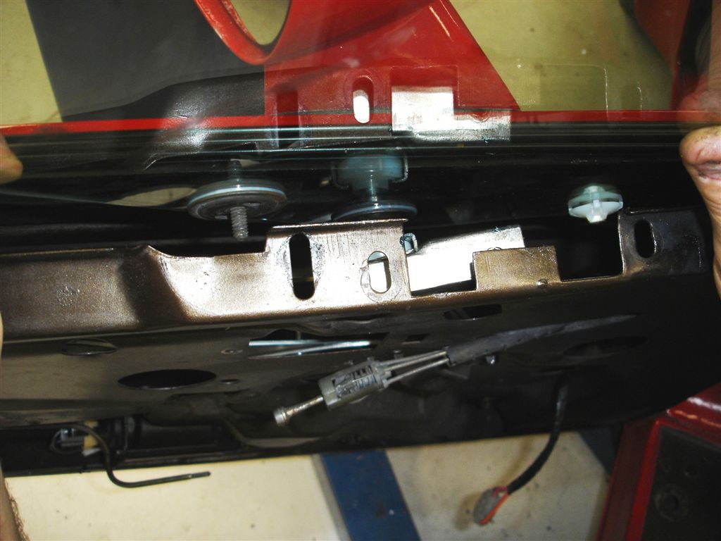
The door glass studs are placed through the horizontal track, followed by installation of the 7/16-20 hex nuts. The front door glass stud has an access hole for nut installation.
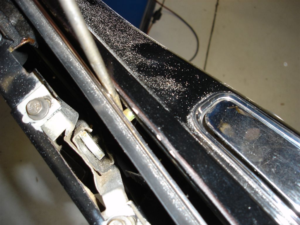
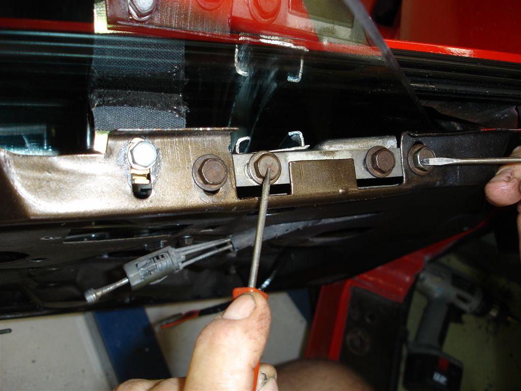
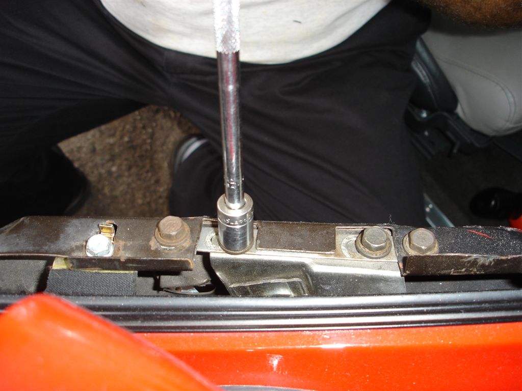
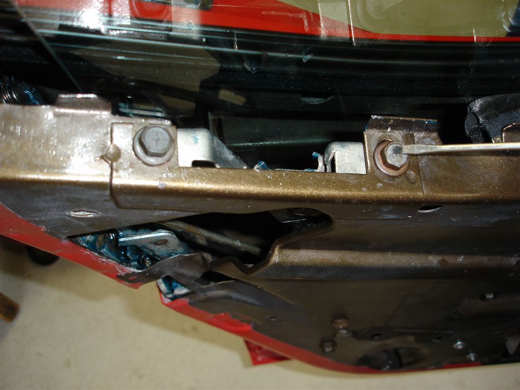
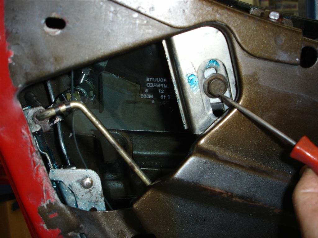
These are the front vertical track adjustment points. The pick is on the screws that allow fore and aft movement of the glass. The small screwdriver adjusts glass tilt at the top. The glass anti-rattle cushion is on front of the vertical track adjuster. Put enough pressure on the anti-rattle cushions to keep the glass off the track until setting the fore, aft and tilt of the glass.
Many of the later C3’s will not allow enough rearward movement of the door glass for a proper fit. This 1979 has the adjuster at the front. If the door gaps are even, but the window is too far forward, open up the slots to allow more movement. The door itself requires some machining to let the adjuster plate move far enough. It is possible to slot the window to horizontal track holes and move the glass. The front roller bearing is riding in the vertical track, so it does not matter where the glass is moved on the horizontal track. This is the compromise we discussed earlier: you have to give a little here and there to make the glass fit and seal properly.
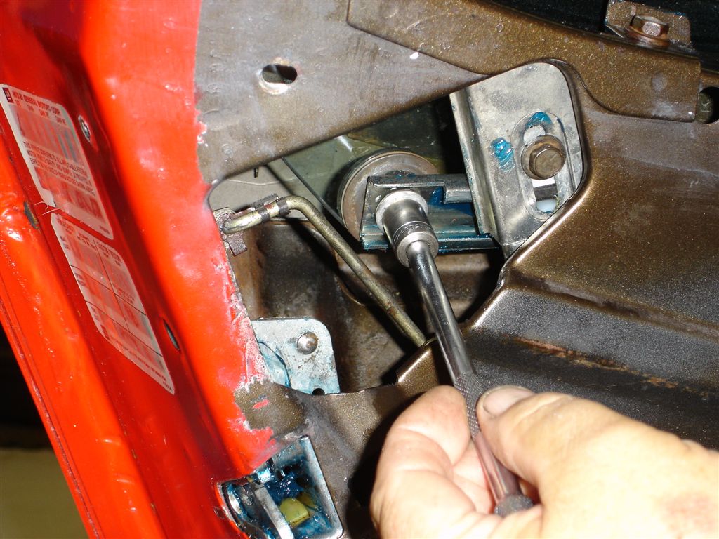
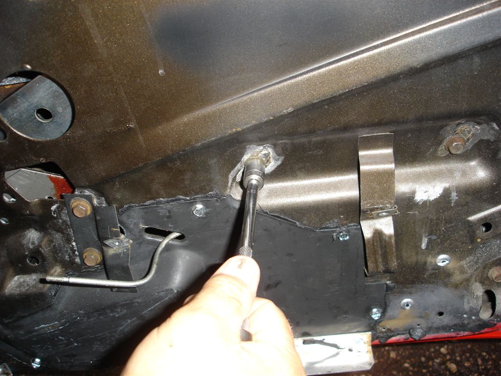
The front lower vertical track has a 7/16” hex head screw holding it in place. The door has a slot to allow some movement fore and aft. We adjust the track so that the window does not bind at the lowest position after all the other adjustments are made.
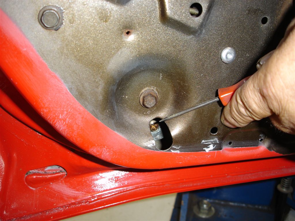
Our rear vertical track has in-and-out tilt adjustment only. We have found that the tilt adjustment must coincide somewhat closely with the front tilt adjustment. It’s not possible to make a major change with the rear tilt while having the front tilt opposite. Too much difference causes binding during glass up and down operation. However, minor changes can be made.
Does the glass need to be higher in the front or rear? Set the glass height with the upper stops. Once that has been determined, watch the glass as it approaches the stops. If the rear is going to come to the stop sooner, move the tilt track accordingly. Do the opposite at the front stop. The glass will be binding during the last bit of operation if this adjustment is not correct.
This is the rear glass upper limit stop. Adjust it so the glass is not buried into the weatherstrip. When positioned too high, the glass catches on the weatherstrip and tears it. The front vertical track has a similar stop that controls upward travel.
The lower stop requires a large phillips head screwdriver for adjustment. Have the glass stop even with the top of the outside seal strip. The glass tilt adjustment may require that the front or rear stop be adjusted differently to coincide with the glass tilt as it comes to its lowest point.
Once all of our other adjustments are made, the anti-rattle cushions are set so that they have light tension on the glass. The outside of the glass should also have light tension at the outside seal strip. We find them either too loose or tight, causing the window to bind during operation.
The rear anti-rattle cushion is set in the same manner.
Door Lock, Latch and Release Handles
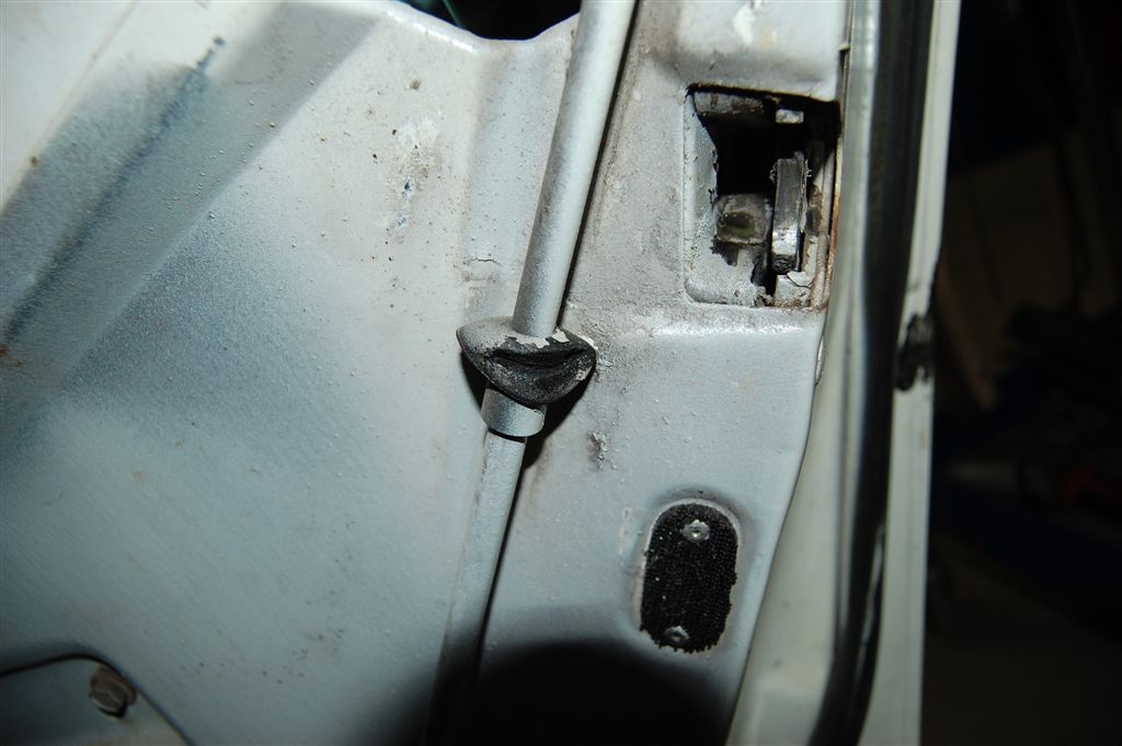
It is definitely easier to service door locks and latched when window glass is already removed. As there is not an easy way to lubricate them periodically, they usually only get serviced after they stop working. The linkages are also prone to wear from lack of lubricating, so it is best to remove and clean them for inspection. Replace the worn anti-rattle grommets to keep the doors quiet on rough roads. All of the retaining clips are available from Corvette Central.
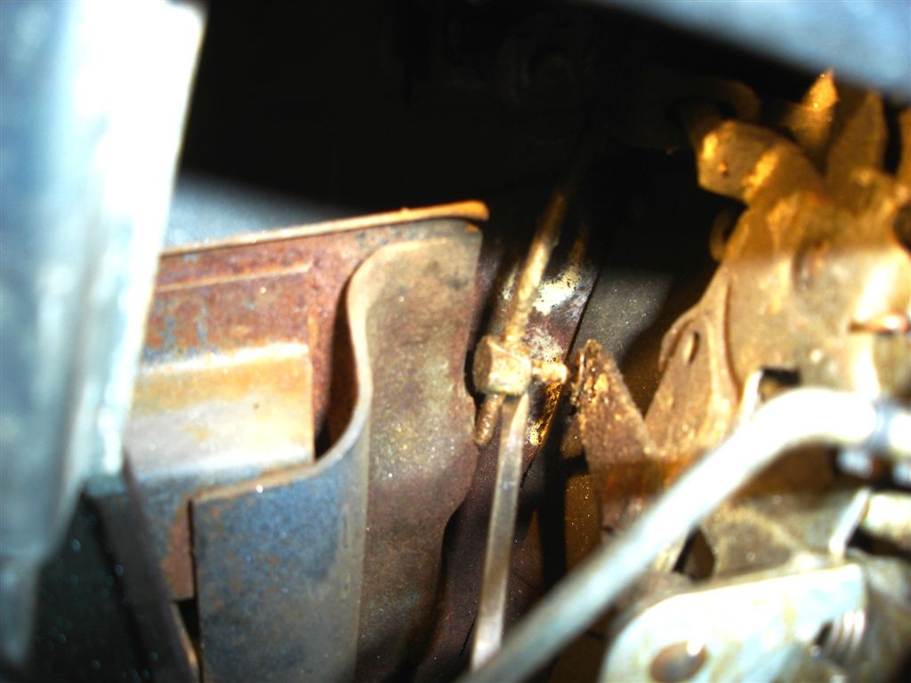
GM used a really nifty clip that allows you to push the rod into the clip. The trick is figuring out how to remove the rod from the clip. The clip has to be backed off the latch/lock assembly then the rod comes out.
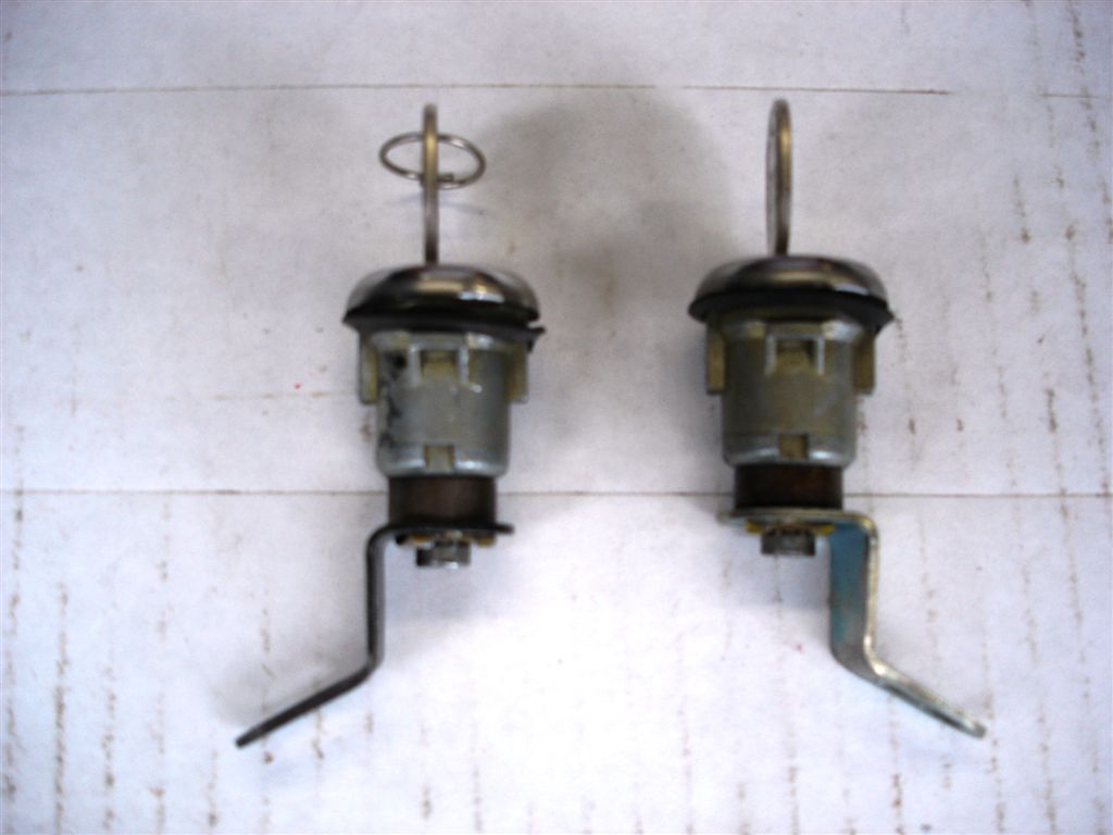
Stiff lock linkages make it difficult to lock or unlock your Corvette. The outside door lock cylinder has a tendency to wear at the lever, making it difficult to unlock. In these photos, we have sourced a complete set of lock cylinders.
78-82 C3s have door lock anti-theft covers. Two phillips head screws hold the cover in place.
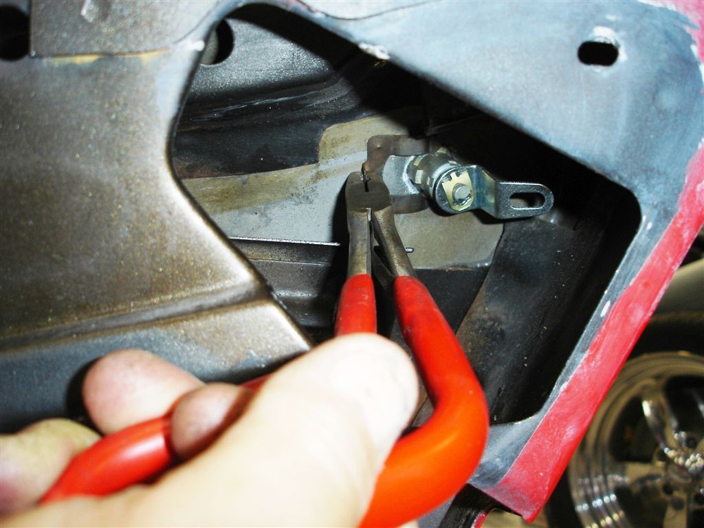
These really unique pliers make it easy to remove or replace the door lock cylinder retaining clip. Be sure the clip goes under the tabs on the lock cylinder and not outside of it.
Our 1979 Project had an aftermarket alarm installed, so we used spacers to take the place of the door lock cylinder switches. The door lock cylinder switches activate the alarm. They would have been sandwiched between the cylinder and the lever.
Pictured is a 7/16” nut. The door handle has two nuts holding the handle in place. If the glass is in place, it is easier to have the window all the way down to access the nuts.
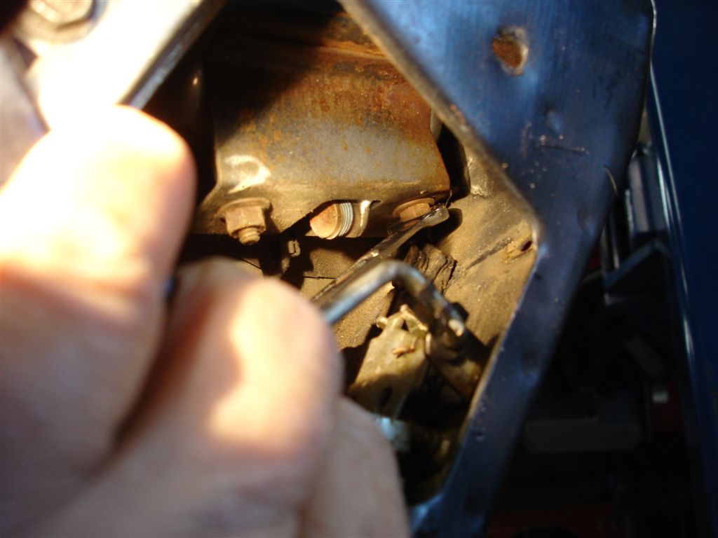
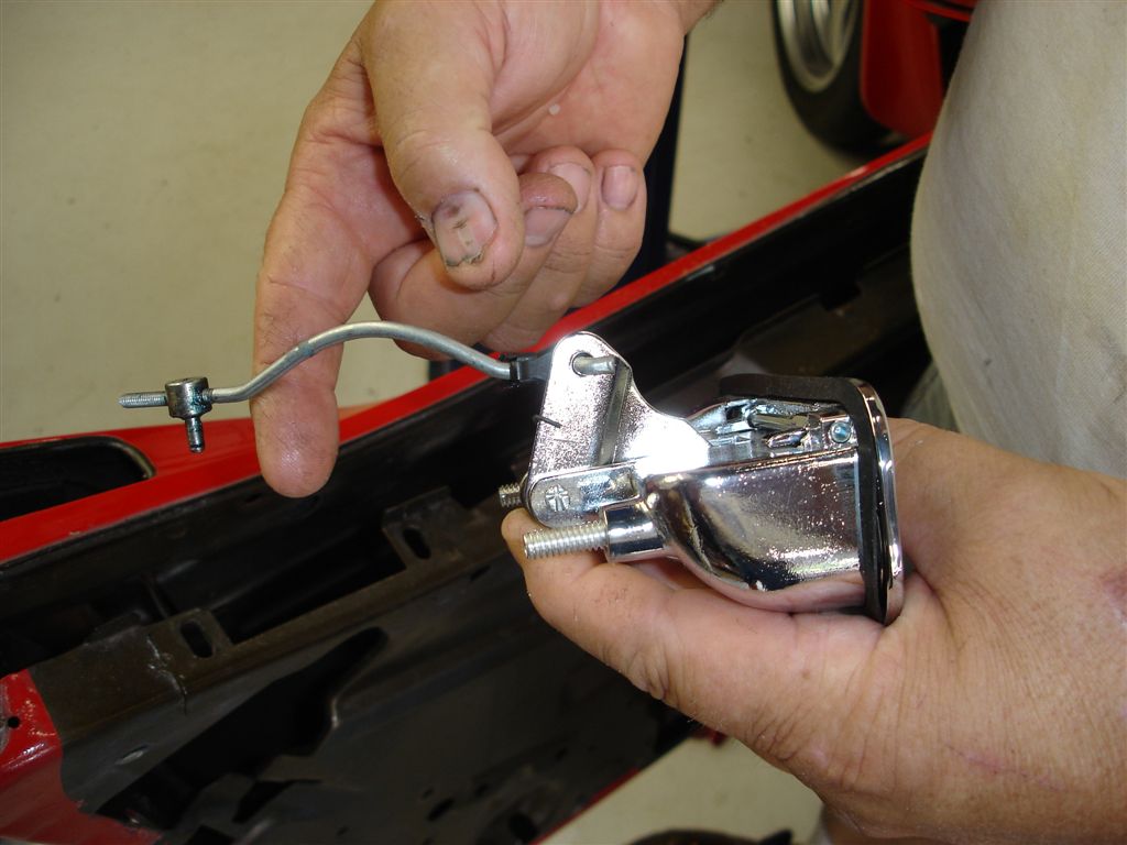
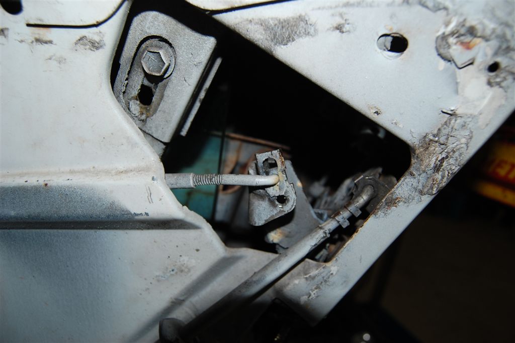
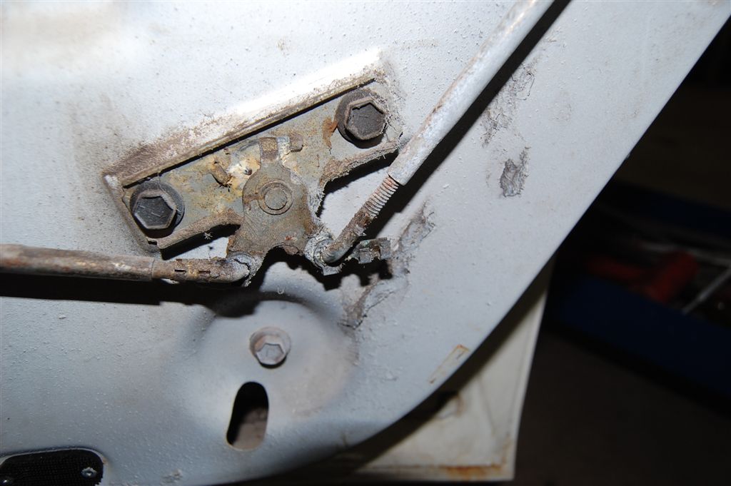
The door handle release rod adjuster pushes into the lock/latch assembly. It is easier to remove the linkage adjuster now, as opposed to removing the rod out of the handle. Exterior paint damage can result during the ensuing struggle.
The pictured clip is an anti-rattle device. Note how the linkage rod’s curvature is up and the handle’s lever is also up. Make sure you orient the linkage this way. When adjusted properly, the outside door release handle should disengage the lock/latch assembly before the handle.
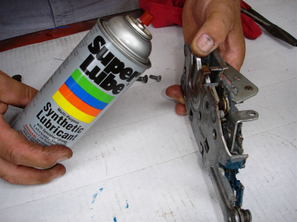
After we clean our lock/latch assembly, spray it down with lubricant to assure deep penetration. Any penetrating lube will work.
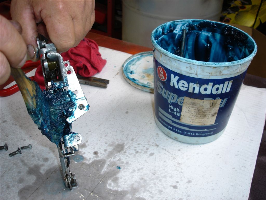
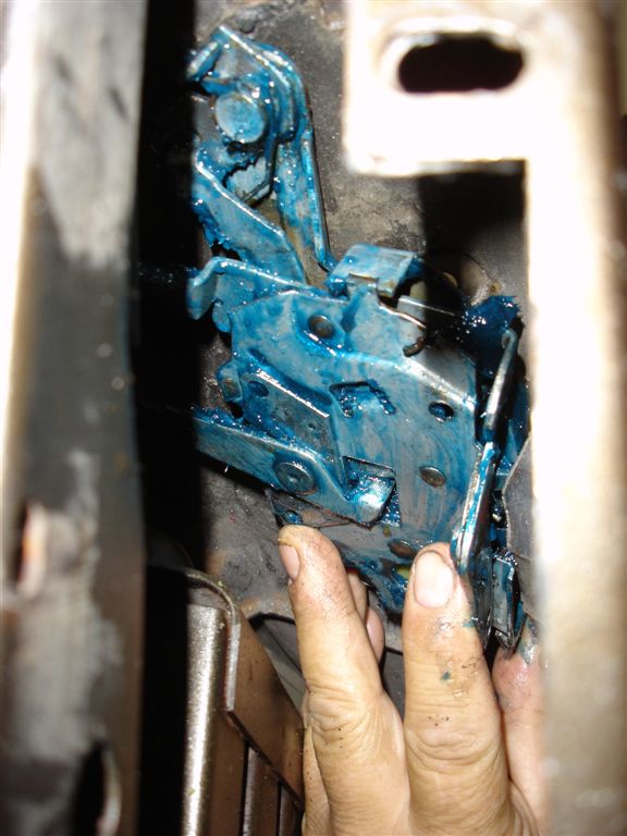
Apply a good coating of chassis grease to the lock/latch assembly to keep corrosion from forming. The grease is sufficient to lube the mechanism, but penetrant really gets down into the pivot points.
The latch is installed with #341048 screws, the correct pieces for 1968-77 cars.
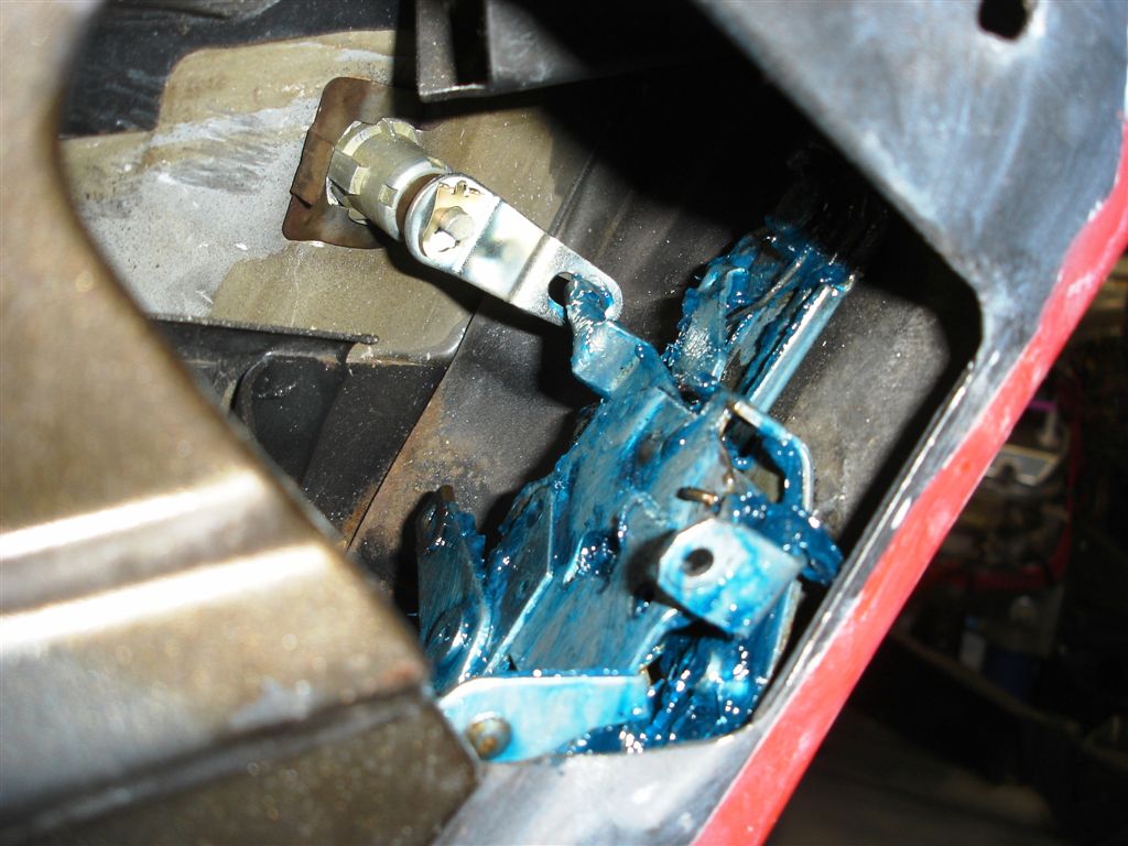
The door lock cylinder must lever must engage the lock/latch assembly’s rod.
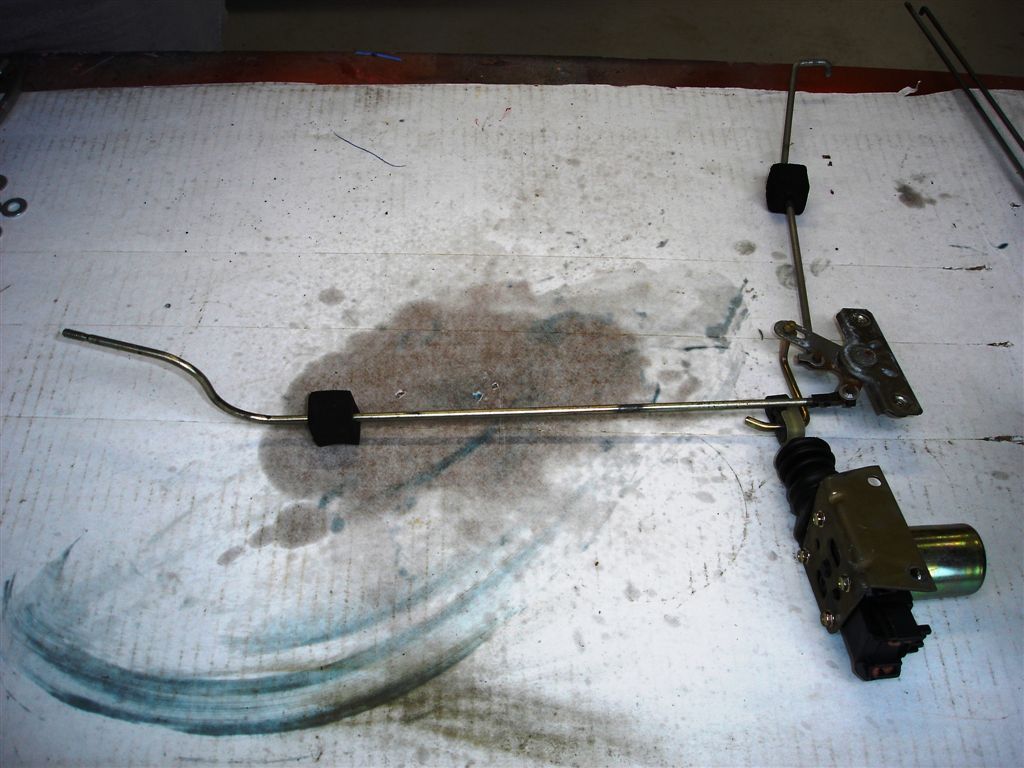
Same treatment on our 1978-82 Corvette linkage assemblies. If necessary, we can replace the worn anti-rattle grommets with item #283026.
This is the 1978-82 door lock linkage out of the door and the approximate way it is installed in the door.
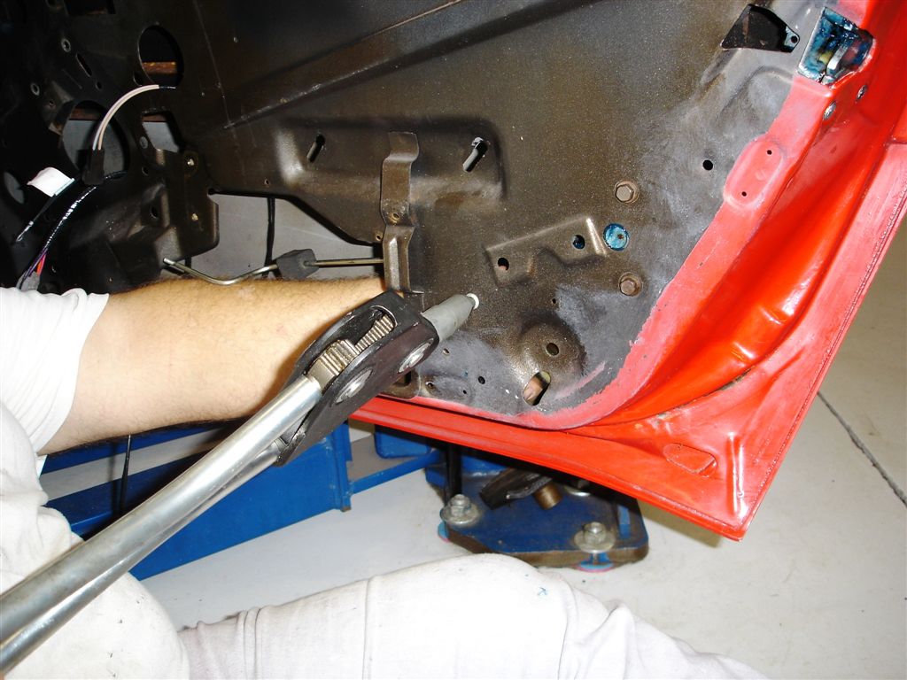
GM riveted the door lock actuator into the door with ¼” rivets. Here we are using our Big Daddy riveter to set the rivets. Many of the tool wholesalers have these rivet guns at reasonable prices.
Our inside door release handle was broken from abuse. Push the linkage retaining clip onto the lever. This clip is sized differently from any of the other clips in the door. Be careful with this clip, as it is tough to find.
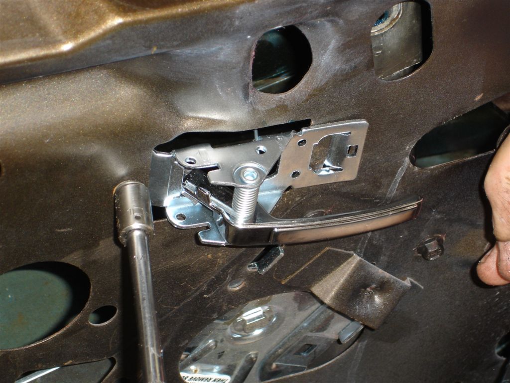
One 3/8” or 10mm self threading screw holds the handle in place.
This early 1968-77 inside door release mechanism is very tough. However, like any mechanical component, they should be cleaned and greased periodically. Some of these door release mechanisms get damaged when the handle is being installed. The mechanism has two pot-metal ribs that help hold the handle in position. Do not force the handle, as the ribs can be broken.
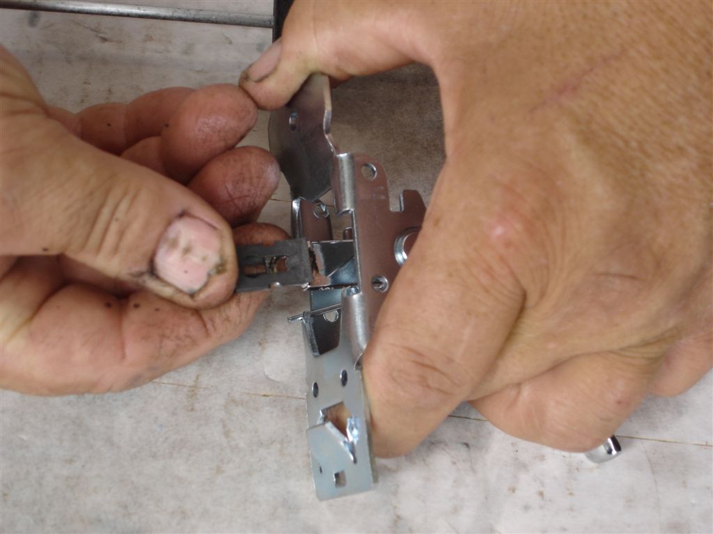
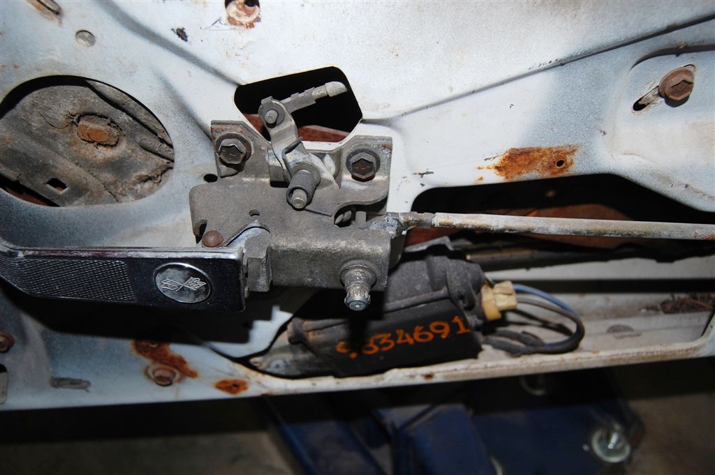
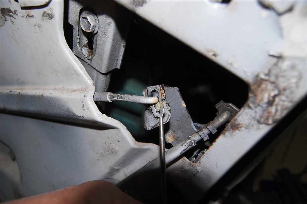
GM used these clips from the early days until the C4. The clip has a small tab that prevents the clip from moving off the lever. In this application, the clip must move upward by lifting the end of the clip. Once the clip is lifted high enough, it can be pushed upward. Once the clip is up, the linkage rod slips out.
Here the clip is beginning to release the linkage rod end. Move the clips up and slip the linkage out without losing the clip off the lever.
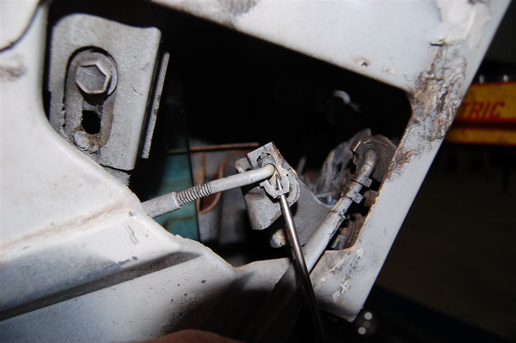
Here the clip is up all the way, positioned to allow the linkage rod end out. This may seem like a lot of time spent on a minor subject. If you have to remove one of these clips from a lever that is somewhat hidden in the door, you can appreciate how to remove one of these clips correctly. The clips are tougher than you think and other things get damaged and possibly the rods get bent and then bind. We replace all of these #282179 clips when we restore any door.
These are easy clips to deal with they pop off the rod end with little effort. These clips come in right and left hand because of there rotation limitations. We have them in both right and left hand item #283077 is left hand #283082 are right hand.
These door lock rod grommets item #283078 are often forgotten, causing aggravating rattles.
Mirror Replacement
If you have all the other items out of the door you may want to remove the outside rear view mirror to replace the gasket or clean under it. Certainly the best way to paint the door properly is to remove the mirror.
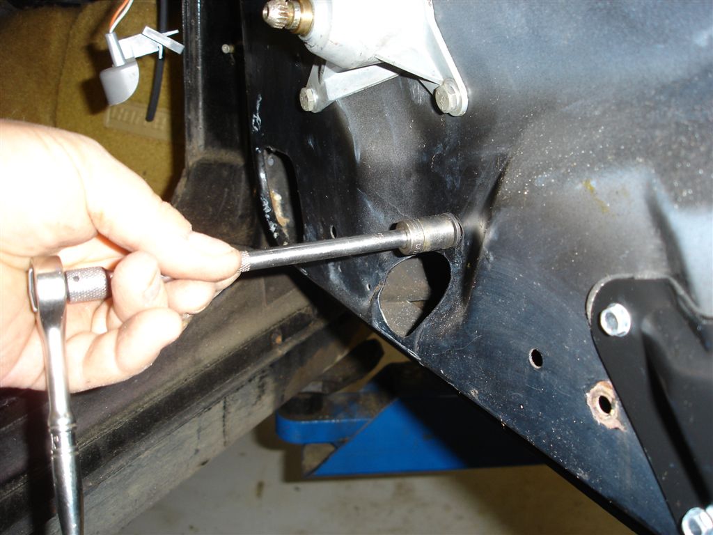
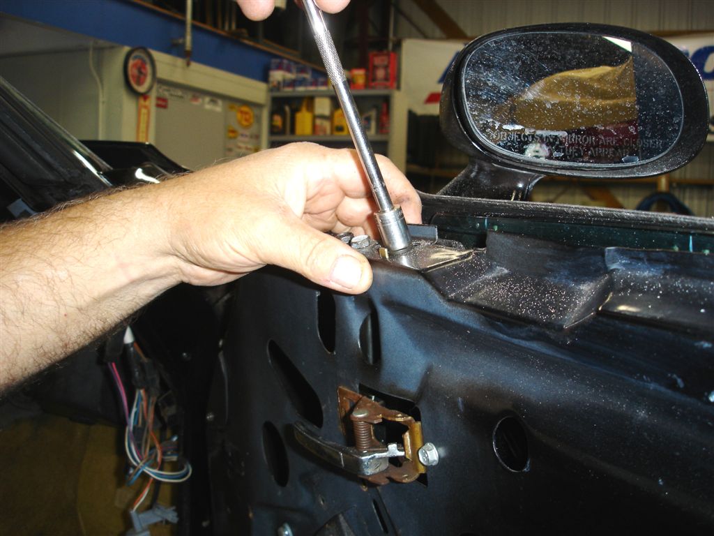
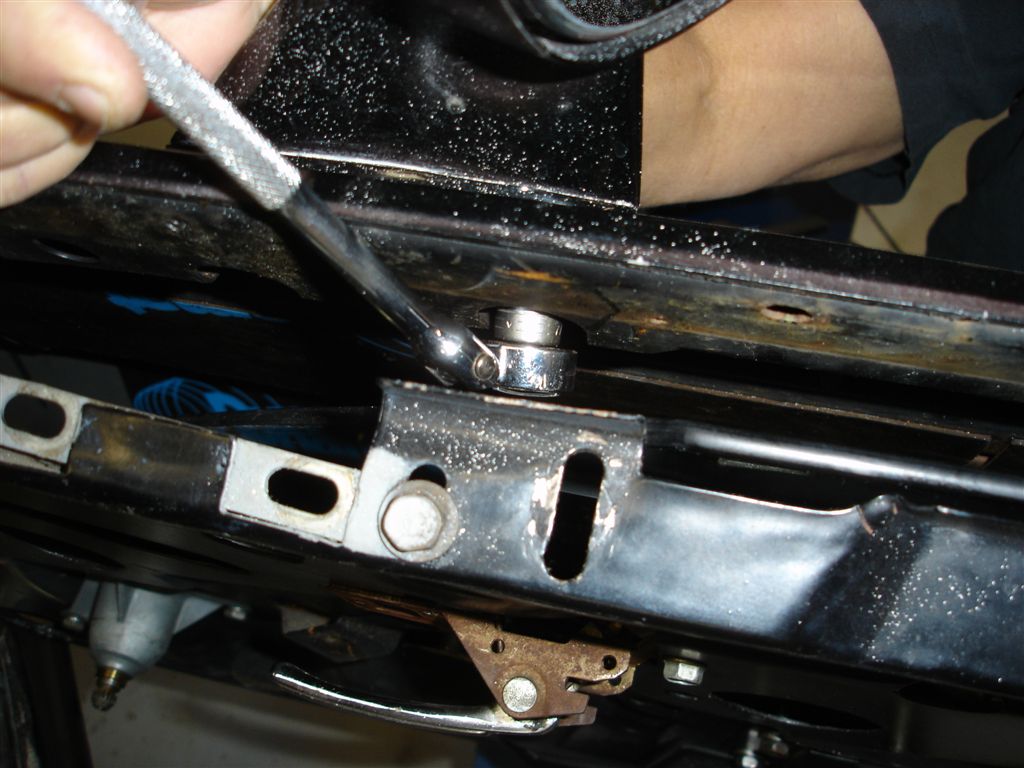
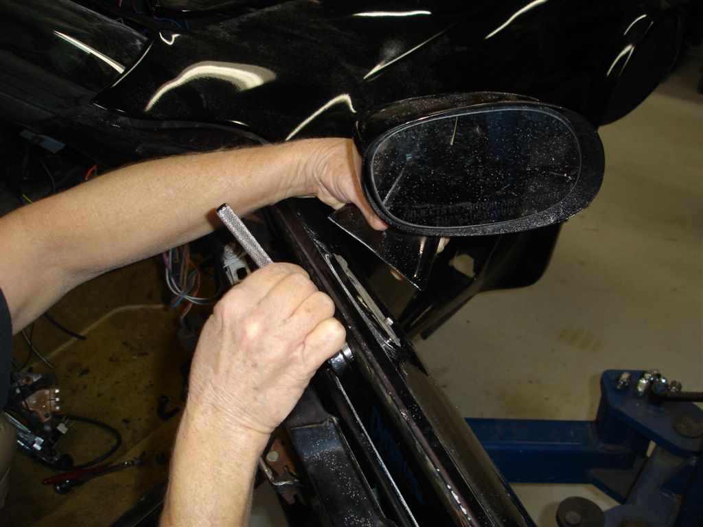
This handy ¼” drive flex ratchet works best to remove the 7/16“ nuts that retain the mirror to the door. As you can see the outside seal strip and stainless steel trim pieces are removed from the door. These pieces do not have to come off to access the mirror retaining nuts but the glass does have to be out of the way.
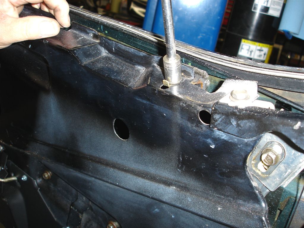
Like usual the stud came out with the nut. You’ll want to be holding on tight to the mirror because sometimes both studs come out with the nuts and the mirror is ready to drop.
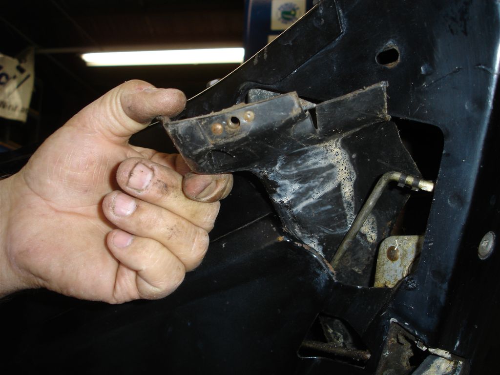
Like this mirror both studs and nuts came out the same way. Remember to put the gasket with the high side to the top. The gasket is often installed with the high side at the bottom then the mirror just about hits the window.
Window Regulator Service
Here you have a few choices: replace the entire regulator assembly? Repair your original? Swap your motor onto a fresh regulator? Whatever direction you take, Corvette Central has the parts that you will need. Remember: if the window does not consistently stop in the same position, it will cause leaks. If the gear itself is replaced, the other pivots can be worn and most likely are. Patching can be aggravating sure the window goes up and down do you want to deal with leaks and poor fitting glass?
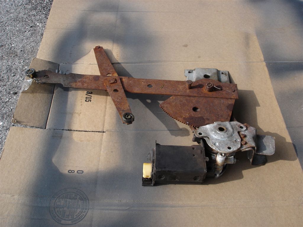
This regulator has loose rollers and worn gear teeth. The window would not close fully, and the gears were slipping. The lift assist spring was also broken, making this window open at high speed.
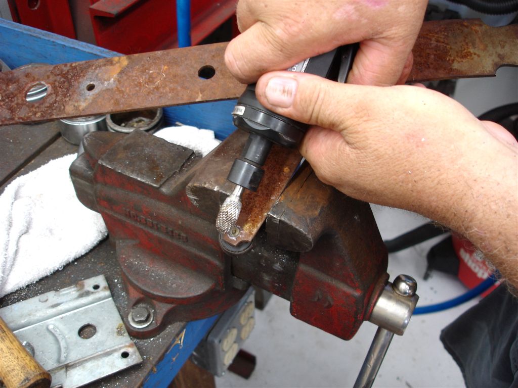
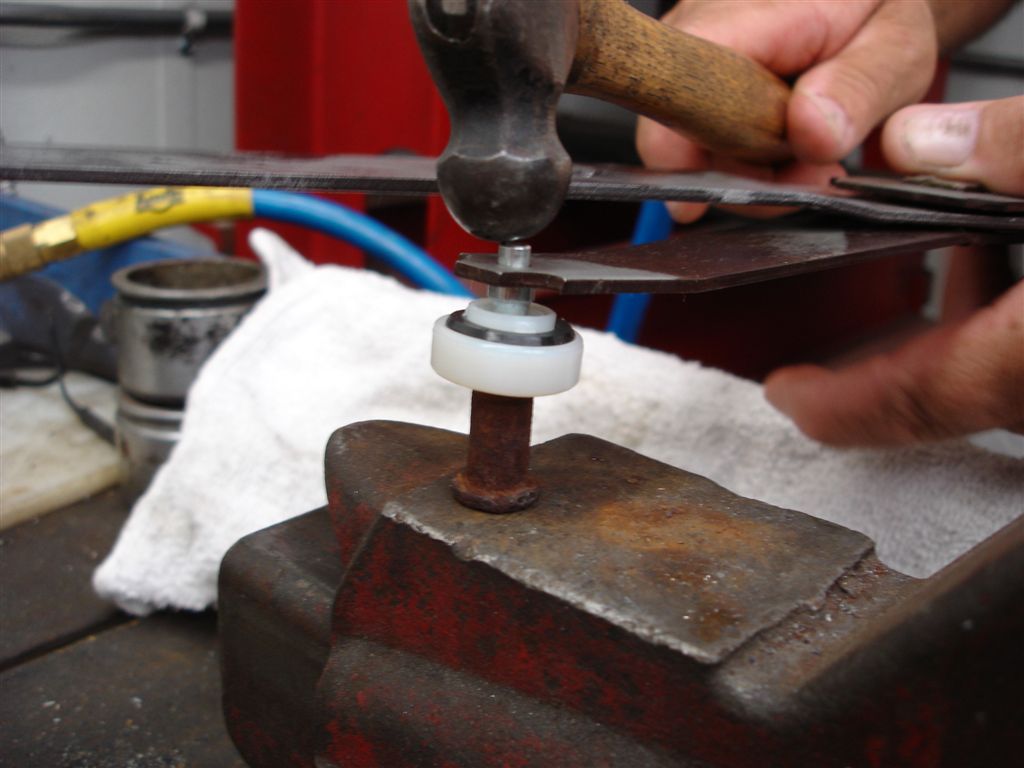
We went for a total overhaul on this regulator. Our high speed die grinder was used to grind off the end of the roller stud.
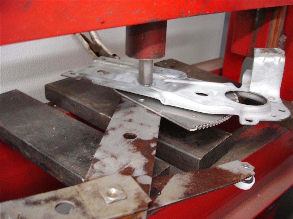
The new roller was held in place with the old assist spring stop pin. Then we carefully peened the end of the roller stud to stake it in place. A hydraulic press would also do the job but the hammer did a fine job.
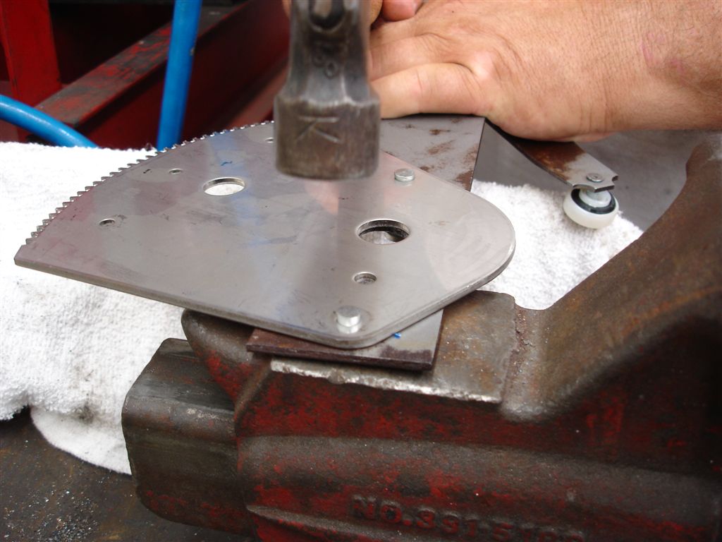
We had to grind off the pins holding the gear to the regulator arm like we did with the roller. Our ball peen hammer worked fine staking the pins to the regulator.
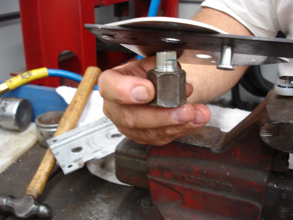
This is our 1963-82 rear strut rod shock mount remover tool. It worked perfectly holding the center pivot pin in place for the staking.
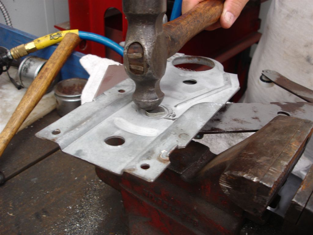
The regulator stationary plate is set onto the pivot pin for staking. If you use the hammer try to avoid missing the pin multiple times during the staking process. Check frequently to make sure you get the pin tight but not too tight causing it to bind.
A piece of double D steering shaft worked well for the staking process in the hydraulic press. As with the hammer, check and make sure the plate moves easily. Avoid overtightening.
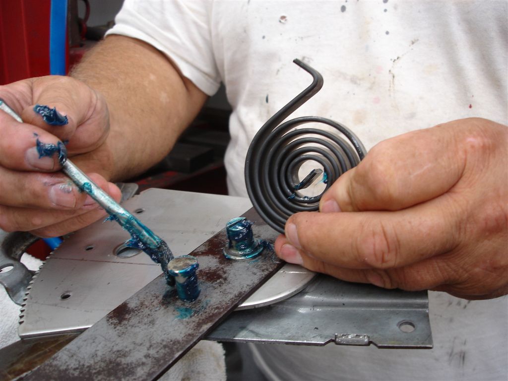
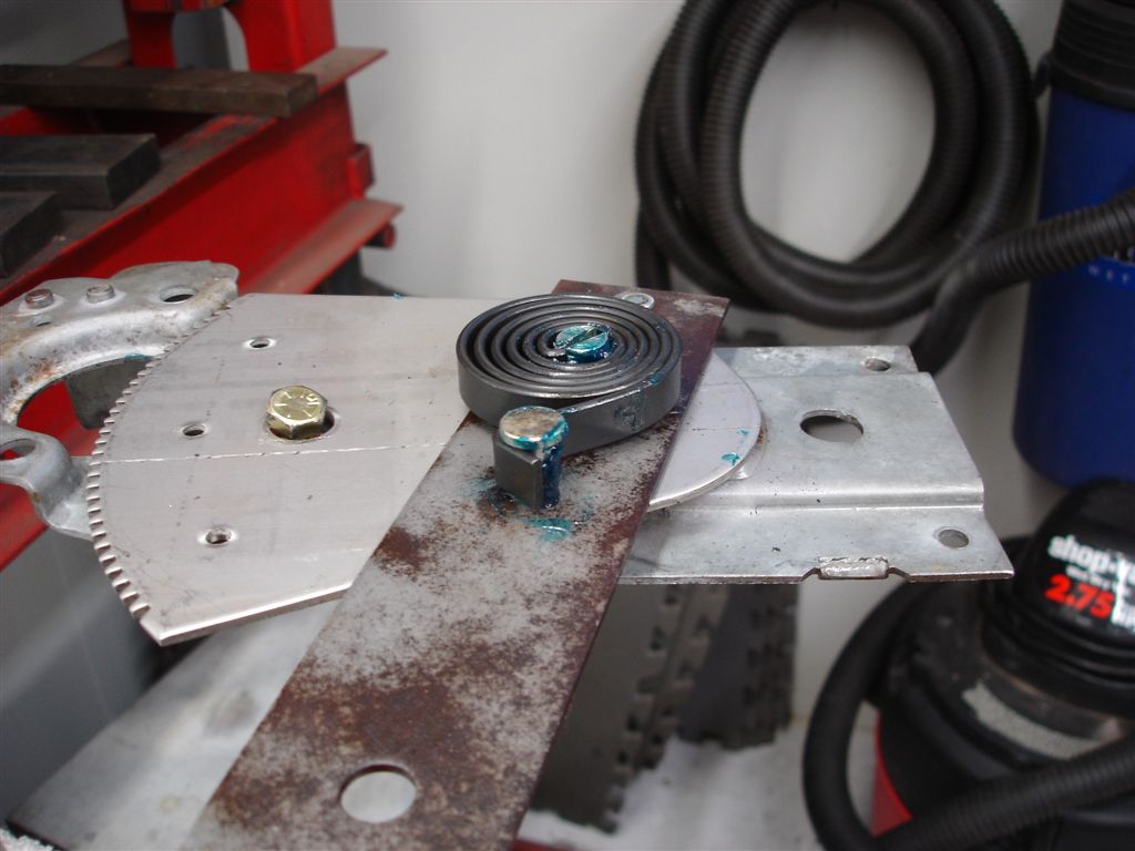
The assist spring is installed. A coating of grease prevents corrosion and noises as the spring loads and unloads.
The regulator is ready for the motor installation. Note the 7/16” bolt head near the gear teeth to keep the regulator arm under control. The spring must be installed so that the assist is for up operation. This is the driver side door regulator with the spring winding correctly installed. Passenger side would have the spring flipped over.
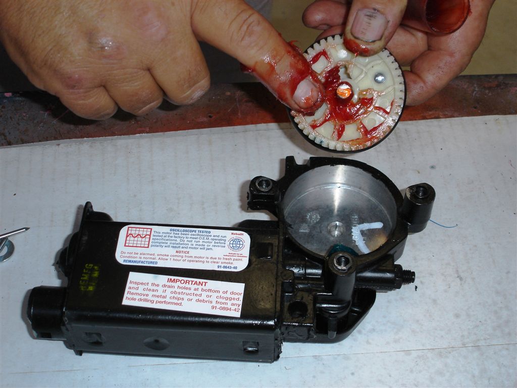
Our remanufactured motor did not come with a gear, so we installed a #283002 gear assembly. The gear comes with the correct lubricant. The new motors include the motor and gear as an assembly.
Once installed, wipe some gear lube on the teeth and seal surface.
The motor has raised areas that fit into the regulator plate. Make sure the teeth are lined up and the motor is set into the regulator correctly. The reinforcement plate has a centering bushing that keeps the gear in alignment. Corvette Central sells the bushing #283136 if yours is missing. Motor and regulator gear teeth damage will occur if this bushing is left out.
Tighten the 7/16” screws and remove the bolt and nut holding the regulator arm. The bolt with the yellow paint daub on the nut is for regulator arm restraint.
Story and photos courtesy Chris Petris

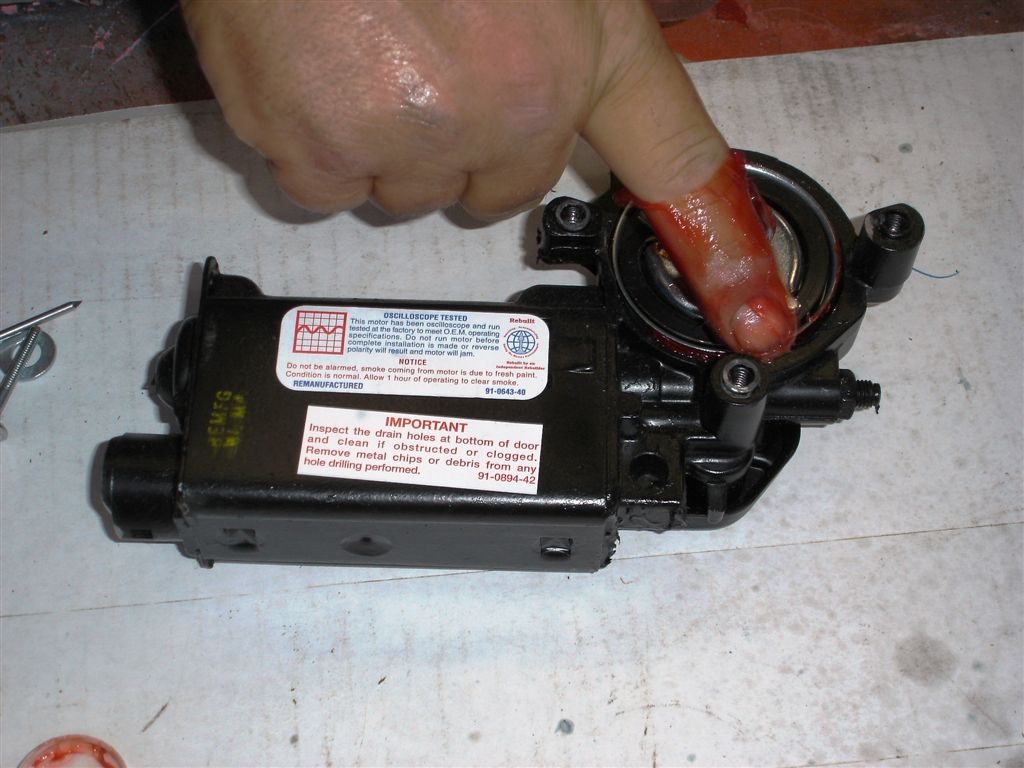
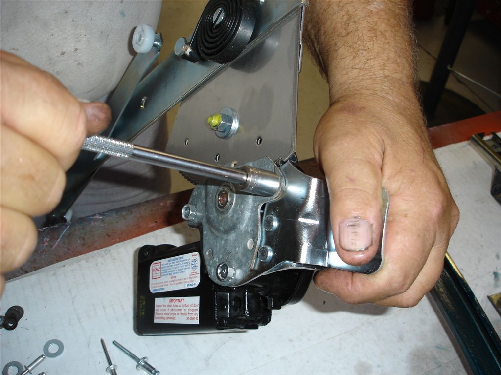
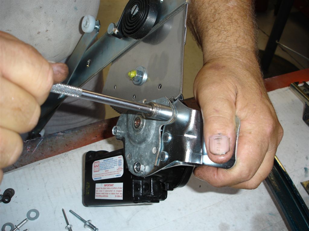
I may have missed it, is there a photo of the hole to pin the regulator/spring in place so I can keep all of my digits?
Great How-To. Thanks! One question: Is the front roller (the one attached to the glass) supposed to roll? I have a replacement that doesn’t roll.
very nicely done ! helped me out alot
I’ve been fighting with my door for 2 days. The initial problem was the rivets were removed previously and someone just run 2 self tapping screws Into the regulator. But any how I pulled it apart installed bolts and cleaned and lubed everything. I proceeded to put it back to heather and came to the adjusting part no matter how much I tried it was messed up. This article explained every nit bolt and adjustment so glad to have found this. I have quit for the day but will let you know how tomorrow goes.
do you have any info on how to assemble and install lower door channel reinforsements for a 1963 corvette coupe?
Unfortunately at this time we don’t have any tech articles on lower door channel reinforcements.
Excellent and very detailed instructions.
Final comment as I rebuilt my window using these excellent helps. On my 81 corvette I had to drop the rear guide out of the way and then there was enough space to get the front roller and front horizontal track stud in. I tilted the window up and fed the glass into the door as there is plenty of space in the rear of the door. It was then just a matter of moving the glass to the front and attaching it to the front guide (also dropped to allow this). No trouble with the attachment or the rear roller which had already been placed into the track. Seems this was the only way to get it into the door.
My Corvette is 1981. Further comment to my previous one: if you buy the glass window rebuild kit (CC# 283084) it will come with the front roller…in pieces. You need two of these for two windows. You will still need to purchase the three rollers that go on the window regulator as they do not come in the kit. There are 6 of these in a package, so there is enough for two windows (CC# 283149.)
Thanks a million for this. I would add a couple of thoughts. When removing the window regulator with the electric motor attached, make sure you put the regulator up as it folds up the regulator. The front roller is sold separate from the lift kits so get them both.
Very thorough instructions but not a lot of help for those of us who have manual windows and want to retain originality. Would be great to know how to rehab a manual regulator.
This door glass rebuild article is very in depth. I just spent two years rebuilding my 76 vette. I did just what you did, I rebuilt both doors, the only thing that I did not change was the window tracks. But now I have a problem with the right door glass. I can not get the glass all the way up on the front corner. There is a little opening right where the t-top fits to the windshield frame, I tried over and over to adjust it up but no joy. I am going to try again. But enough about me, I just want to tell you did a great job on this article.
Thanks for the great article. I noticed on your web home page. I bought glass from you last year. Just now getting ready to install them. The article will come in handy. Much Thanks…Marco
very thorough step by step instruction——-thanx jeff