Corvette Central’s Split Mod chassis will be headed to the 2012 Corvette Expo (Houston, Texas) in February. To bring you up to speed, the 1963 split-window coupe had no engine or transmission when it was rescued. The severely rotted chassis has been replaced, and now we are working on the drivetrain. Corvette Central had a complete 1986 Corvette convertible L-98 engine and transmission assembly stored away, making it a perfect candidate for Project Split Mod. The 700R4 transmission that was coupled to the L-98 was mothballed to be used for a later project. Gear changes would be transmitted through a Keisler Engineering RS400 five speed overdrive transmission. There were many reasons for the engine choice, other than the fact it was sitting in storage waiting for someone to use it. Aesthetics were a concern, what with all the recent LS engine transplants under the hood of early Corvettes. It made sense to have a traditional look.
Technically, the decision was easy: the 1986 L-98 engine is the first year of the Generation Two (Gen 2) architecture, with roller hydraulic lifters and aluminum cylinder heads. Only 1986 convertible Corvettes had the Gen 2 L-98 with roller cam and aluminum cylinder heads. Corvette coupes did not receive the Gen 2 engines until 1987. The Gen 2 engines had another attribute that made them less problematic over the long haul. Gen 1 engines were prone to oil leaks, while Gen 2 engine blocks and cylinder heads were redesigned for better long term oil retention.
The Gen 2 engine block, or “case” as GM calls it, was redesigned with a one-piece rear main seal replacing the original two piece rear main seal. To accommodate the new one-piece rear main seal, an internal balance crankshaft replaced the 31-year external crankshaft mainstay. No parting line between the one-piece rear main seal and rear seal housing meant a tight seal, even at high RPM. Rear main seal leaks were finally a thing of the past. Another first was the use of a one-piece oil pan gasket to take care of all the original bottom end leak concerns.
The hydraulic roller lifters required engine case modifications to prevent camshaft walk. Early flat tappet engines before 1986 had no way to prevent the camshaft from moving forward and rearward in the case. High performance engine builders that wanted to use roller camshafts used various ways to prevent camshaft lateral movement. One popular and inexpensive option in preventing camshaft movement was a nylon thrust button that displaced the distance between the end of the camshaft and the timing cover. The next solution was a specialized high performance water pump, designed with a machined boss utilizing a bolt to prevent timing cover flex. Full race engines went further, utilizing roller bearings to control camshaft movement. This required a modified camshaft driven gear that allowed the use of two Torrington roller bearings. One roller bearing was placed between the camshaft gear and engine block for the cam gear to ride against. Another bearing was used to replace the nylon thrust button.
GM simply added a plate that was sandwiched between the camshaft driven gear and engine block. No more camshaft walk, so the hydraulic roller lifters would stay centered on the camshaft lobes. Another concern was the hydraulic roller lifter, which would require a camshaft that would withstand the new lifter’s hardened roller wheel. Now, that seems easy enough. Hardened camshafts have been in use for many years in race engines. However, things are never that easy. The camshaft’s distributor drive gear must be compatible with the iron distributor’s driven gear. Race engines use bronze distributor driven gears which are sacrificial, not something that the typical vehicle owner wants to hear. This means that the hardened camshaft would require a cast iron gear to allow long distributor driven gear life. GM worked out the problem, utilizing a cast iron distributor drive gear with the hardened camshaft.
The next concern was that the taller roller lifter would require control of lifter rotation, to keep the roller lifter wheel headed in the right direction. Roller lifter guide plates were used to prevent lifter rotation, with a metal retainer holding all the pairs of plates in position in the new design lifter valley. The taller lifters would require shorter pushrods to keep the external dimensions close to the original Gen 1 architecture.
A great advancement was the cylinder head redesign to center bolt retention. The raised valve cover rail made a huge impact. For the first time in 30+ years, the valve cover gaskets were not swimming in engine oil, causing constant oil leaks from the valve covers. Gen 1 engines will have oil leaks at the valve covers when using original cork material gaskets; it’s a matter of fact. Today, Corvette Central has better gaskets available which are composed of high tech materials. Careful installation is the key, which is another story to be covered later. For the first time, the raised valve cover rails would allow small block engines to go beyond 100,000 miles without multiple gasket replacements.
The aluminum cylinder heads were lighter weight, although they did not perform much better than their cast iron counterparts. Removing weight from the front end of any vehicle is a good thing, to aid in vehicle balance. The aluminum cylinder head design had valve train lift limits when high performance camshafts were used. Any camshaft
with more than .490 maximum valve lift could cause valve spring coil bind, causing the valve spring retainers to crash into the valve guides. It is very important to check coil spring bind and valve guide to retainer clearance when choosing a performance camshaft. Most high performance camshafts have gross valve lifts in excess of .500 with vague warnings about any clearance concerns.
To sum things up, the second generation Chevy small block took care of many of the Gen 1 engine’s annoying issues. We all know the 32-year run of the Gen small block was phenomenal, making great reliable horsepower. There are plenty of the Gen 2 engines in the field, so to speak, making them an excellent candidate for a rebuild.
The next concern: what fuel system do we use? Carburetors like the Gen 1 engine worked well for years. For the best all around performance, Jerry Kohn, founder of Corvette Central, wanted fuel injection, and considered using the tuned port fuel injection from the 1986 L-98. Jerry really liked the look of the tuned port intake and valve cover fins. We discussed a few other possible fuel systems, with Jerry knowing that there are better systems available. The L-98 tuned port intake manifold has 17 inch intake runners, making them excellent for low end torque. The problem is when the RPM is above 4500 and the long runners suffocate the engine, cutting back on power.
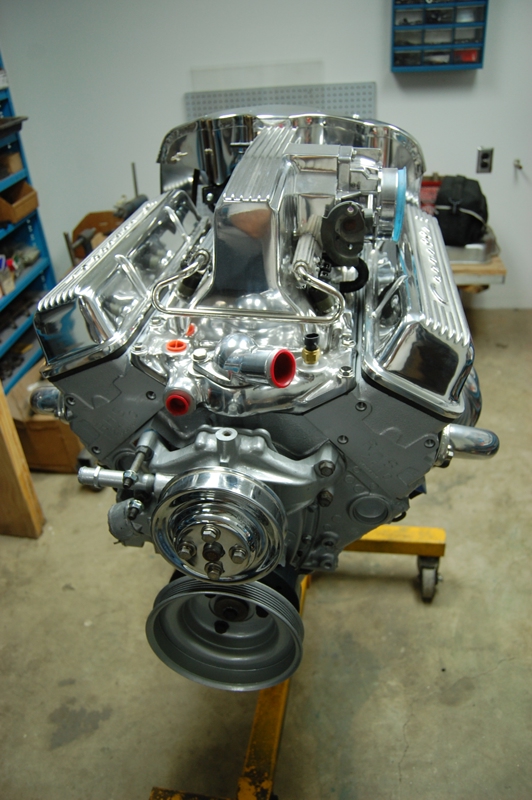
Chris’ preference was the Arizona Speed and Marine Superjet intake manifold that resembles the original fuelie units of the Solid Axle and Midyear era. GM introduced the Ramjet electronic fuel injection fuel system to be installed in pre-1973 vehicles. This manifold looked quite a bit like the early Ramjet from the solid axle and Midyear time period, the exception being a front mounted throttle body. Arizona Speed and Marine starts with a Ramjet manifold, modifying them by moving the throttle body to the driver side. AZM also offers a machined intake top, lowering the front profile, along with a finned top surface. The AZM Drop Top intake allows the modified manifold to fit under the Solid Axle or Midyear stock hood. Although not an exact reproduction of the early Ramjet intake, the Superjet dropped top manifold is a great alternative.
Electronic fuel injection with an original look would be a great fit for Split Mod. The Superjet uses GM sensors, fuel injectors and a MEFI electronic fuel control unit. Once we made the decision to go with the Superjet intake, Jerry had one request that made great sense. Jerry asked AZM if they could modify the fin spacing on the intake top to resemble the 1963 fuelie unit. The Superjet’s side mounted throttle body, custom dropped top and new electronics made sense for Split Mod. You know how it goes, you make one change and others follow. Well, the Superjet is no exception. When GM cast the Ramjet, they used the Vortec cylinder head platform. The Vortec cylinder head port runners are higher for better airflow, making the Vortec cylinder head a better performance choice. Although the Vortec cylinder head ports are similar in their configuration to the Gen 1 engine, the bolt pattern is different. So that means our Superjet manifold choice would require Vortec cylinder heads, which will also give us the best possible performance.
After some careful thought about which cylinder heads we should use, Racing Head Service Vortec cylinder heads made sense. The RHS cylinder heads are lightweight cast iron, trimming some front end weight when considering the original 327ci specifications. We chose 12410-02 assembled RHS heads with 2.02 intake and a 1.60 exhaust valve diameter. The RHS heads allow .600 maximum valve lift, so this will let us use just about any lift camshaft a street engine would allow. All new valve train components make this a smart decision to couple with the Superjet intake manifold. The 64cc combustion chambers, flat top pistons with 4 valve reliefs, and .032 compressed cylinder head gaskets will result in a 9.45 compression ratio. Like the intake choice, the cylinder heads require some thought to make them work with our valve cover choice.
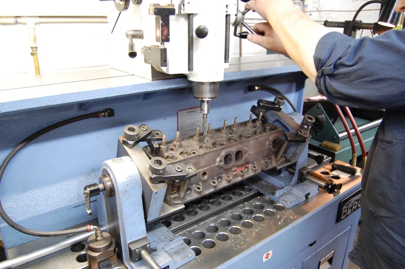
We have included photos of the necessary machine work of original equipment cylinder heads of the era. This will give you an idea why it sometimes makes sense to go the new route.
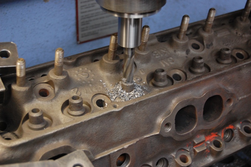
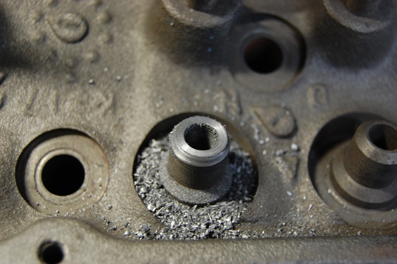
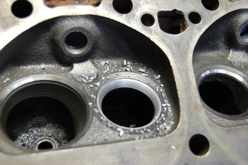
This is the alternative to using the new cylinder heads: machining each of the OE cast in valve guides for inserts. There is an alternative to installing valve guides called knurling; cutting a spiraling groove into the guide. As the cutter moves through the guide, it raises the guide’s material, tightening the valve stem to guide clearance. The knurling process is not long term though. It works for a while, but the valve stems will loosen in the guides again.
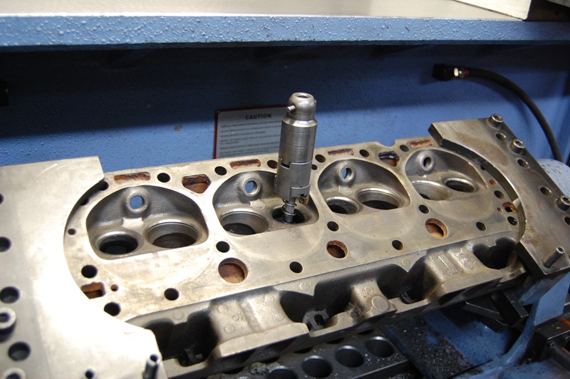
The milling machine takes a while to set-up for the correct angle and position, making this procedure costly, but it will save a set of numbers matching heads, if that is what you want. The best policy is to have all the guides replaced for like new performance.
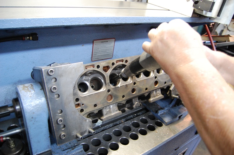
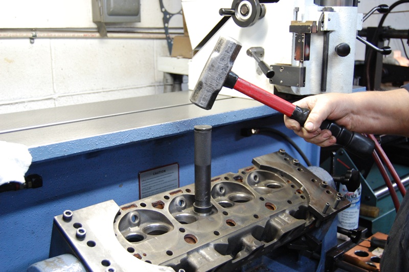
An air hammer is used to push the guide insert into the cylinder head.
A cutter is used to machine the top of the installed guide even with the original guide. This same cutter can be used to provide additional clearance for high lift camshafts.
The finished guide cut down to the original height, ready for valve seat machining. The new valve guide inserts have rifle drilling to keep the valve stems lubricated.
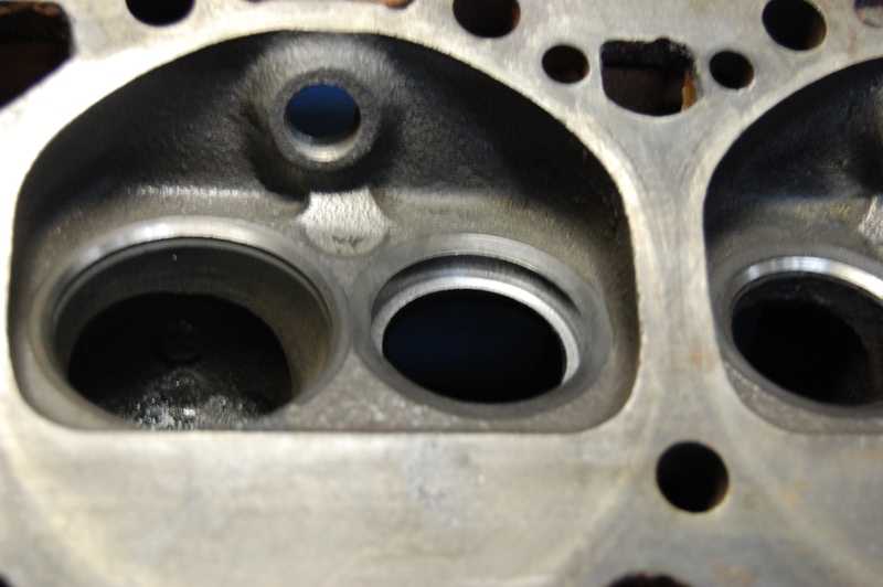
The next process will cut out the cast-in valve seat after the guide work has been completed. Cast-in valve seats must have hardened seats installed to allow unleaded fuel use.
Machining depth is critical or you will find coolant in the exhaust. We recently had another machine shop install hardened seats. When we finished up the project, coolant was coming out of the exhaust pipes with smoke billowing out the exhaust. Although there was a possibility that the cylinder heads could be repaired, we had to find another set.
It takes a lot of force to install the hardened seats into the freshly machined seat pockets. By the time you have all the guides and seats installed, it gets pricey. You should check the costs carefully before making a decision whether to use the original cylinder heads.
The hardened seats are rough cut to be machined after installation.
This small block cylinder head will receive a four angle performance valve job. As you can see, it takes a lot of labor and pieces to properly restore early cylinder heads.
Jerry wanted to use a really cool looking, highly polished set of specialty valve covers. He chose raised letter Corvette script valve covers with seven fins (Corvette Central part number 301239). The finned covers would accent the intake’s fins, bringing the entire look together. The perimeter valve covers would not directly fit onto the RHS Vortec center bolt cylinder heads. We would have to use center bolt to perimeter bolt valve cover adapters. The adapters are designed for stamped rocker arms, so we would be doing some notching to use our adapters with the Comp Cams full roller rocker arms. When you get into projects like this, all of these small items need to be carefully thought out before any assembly begins.
Now we need to figure out our engine internals, so we can move ahead with machine work and assembly. A trip to the machine shop with the L-98 engine block and the rotating components is next. The crankshaft looked like it would require grinding to bring
back the main and connecting rod surfaces. The machinist verified the grinding requirements after some micrometer measuring. The cylinder block would be bored to 4.030 oversize to clean up the cylinders. We also had the line bore of the engine block checked and machined if necessary. The line bore concerns the relationship of the crankshaft to the cylinder bores. During mass production, the line bore may be off the centerline of the crankshaft, changing the compression ratio slightly. Race engine builders want all the cylinders to be as close as possible to each other in compression.
Precision line boring also assures the least amount of drag on the crankshaft (e.g. if one of the main bearing webs has changed height from long term heat cycling). While we were checking all the possible engine alignment issues, it made sense to see how the cylinder head surfaces were in relationship to the crankshaft centerline. The engine block deck surfaces can be distorted from heat cycling, especially between each pairing of cylinders. Like the crankshaft line bore, the deck surface relationship to the crankshaft can affect compression. Machinists assemble the engine with the crank and pistons and then the cylinder head deck to top of the piston clearance is checked. The clearances are noted and then averaged so a machining depth can be established. We went for the entire checkout and machining process, including the line bore and deck surfacing.
We would have to decide on and supply the pistons before the boring process can begin, as the machinist uses them to measure final piston to bore clearance. We chose Sealed Power hypereutectic 4.030 pistons from their engine rebuild kit, part number CSMHP762-311. This kit comes with pistons, poly coated rings, oil pump, complete Fel-Pro gasket kit, freeze plugs, rod, main and cam bearings. The kit also supplies Plastigage for checking crankshaft bearing clearance and assembly lube for safe engine break-in. Our kit came with the later style millimeter spec piston rings that are much thinner than the typical fractional rings. Thinner piston rings mean less drag, promoting better fuel mileage and more power. The downside to the thinner rings is they are fragile taking extra care during assembly. While we are waiting on the machine shop to complete their work we can prep all the other required engine components.
Our prep consisted of cleaning and painting the parts before assembly. We decided to paint the engine silver, similar to Split Mod’s exterior. We used acrylic enamel single stage paint for application to all the engine components. Once all the pieces are gathered and the painting completed, we can start assembly. The machine shop called to let us know the pieces were ready for pick-up. We have all the components together in the engine assembly room, or clean room as we call it.
Tech tip:
We have a few notes on adjusting valves concerning finding TDC (Top Dead Center) before we get into the assembly. TDC can be determined as the crankshaft is being rotated, watching for cylinder number one intake valve to open. After the intake valve opens and then begins to close, watch the harmonic balancer timing marks as you rotate the balancer. As the intake valve closes, the zero or TDC timing marks should line up as you approach TDC. Once the timing marks are lined up, you can adjust number one intake and exhaust valves. Once the first cylinder is adjusted, the next cylinder in the firing order can be adjusted. We rotate the crankshaft, watching for the number eight intake valve to close. After the valve closes, we put a probe into the spark plug hole and feel for the piston to reach TDC. When the piston is at TDC, we adjust the number eight valves. To sum things up, at every 90 degree point of rotation after TDC is found, it allows you to adjust the valves in firing order. What you have to be careful of is rotating the crankshaft too far or not far enough, which would throw off all the remaining valve adjustments. That is why we feel each piston’s progress as it approaches TDC.
Follow along as we assemble the engine for installation into our rolling chassis.
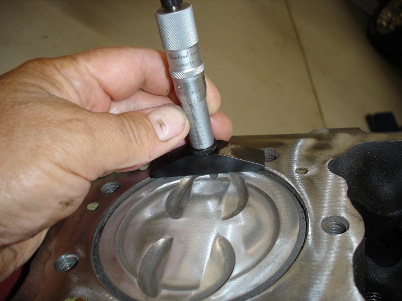
We are measuring the piston to deck height before we do any deck machining. Each corner should be checked and the depth recorded, then averaged for the machining. We try to get as close to zero deck height as possible during the machining process. This raises compression and helps to limit pre-detonation.
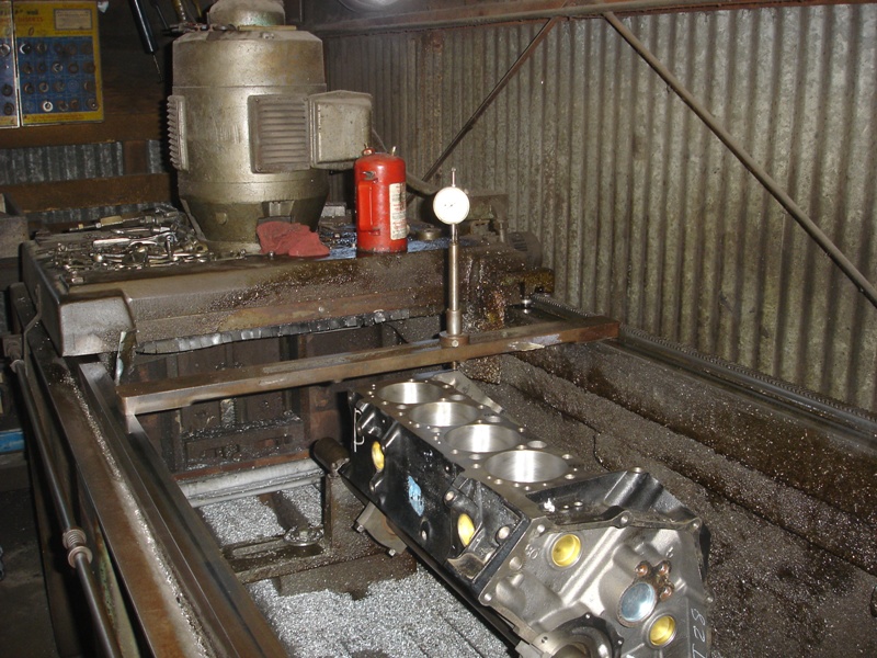
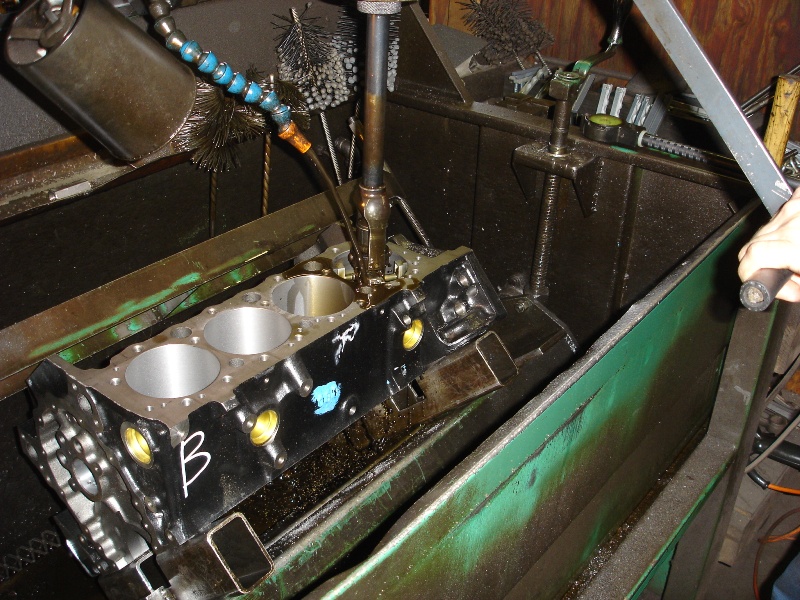
This is the surface grinder with a small block being set-up for the deck machining. The machinist takes a lot of time setting up the block before any machining can begin.
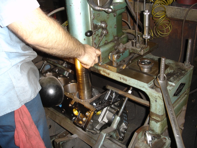
The boring bar is removing material to straighten the cylinder bore and assure round cylinders for quick piston ring seating. This procedure takes careful control so there will be adequate material left for the final cylinder honing.
Now the hone is used to fit the pistons to the cylinders. We are using hypereutectic cast pistons with coated skirts requiring .0015-.002 piston to cylinder wall clearance. Forged pistons require .004-.005 clearance to keep them from scuffing the cylinder walls at normal engine operating temperatures.
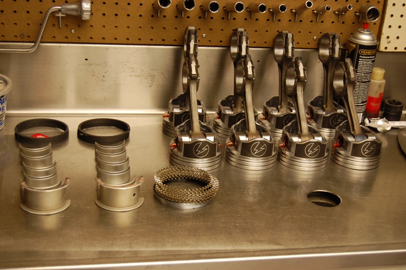
We use this stainless steel bench top to set-up our engine build components. Clean and orderly is the smart way to build engines. Sandy, greasy components will cause plenty of problems during the build.
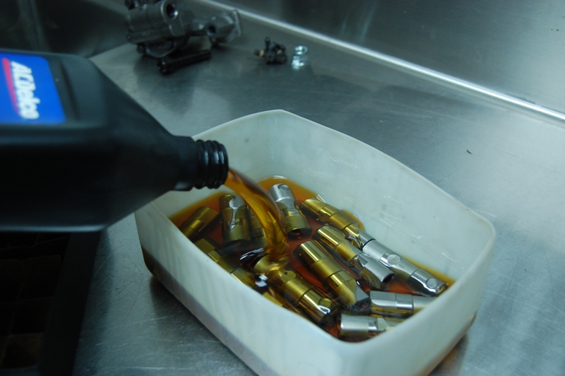
Our new Comp Cams roller lifters are soaked in fresh engine oil and set aside for installation later.
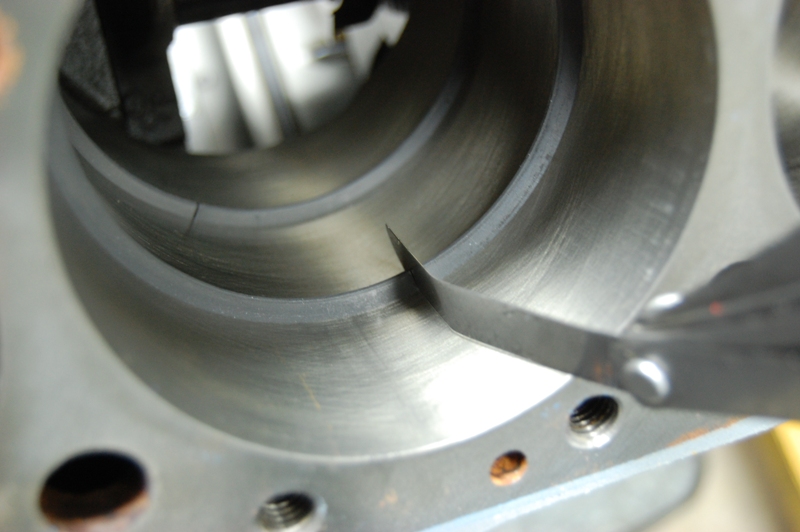
We check piston ring end gap on every engine built. Typically .004 per inch of cylinder bore is the required end gap. Check your piston ring manufacturer recommendations and try to maintain the low side of the required gap. We check each and every piston ring in their respective bore. You never know when an anomaly has occurred during the ring manufacturing process. This also allows us to check piston fit in each cylinder. The machine shop or parts manufacturer will not be responsible if you do not check the basics during assembly. The end of the ring can be filed to add extra clearance. Keep the ring end square and go slowly until the gap is correct.
Piston oil control rings can get you into trouble during the assembly of the upper and lower scraper rings around the center tension ring. Make sure the ends of the tension ring do not overlap. Watch the scraper ring gap placement. They should not line up where the center tension ring end gaps come together. We stagger them so that they are on either side of the center tension ring.
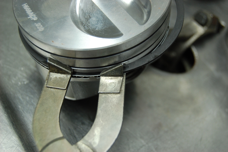
Now we take the rings out of the respective cylinders we checked for correct end gap. Then they are installed on the pistons with this ring installer. Open up the rings just enough to slip them over the piston.
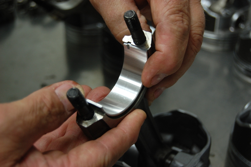
The rod bearings are installed in preparation of piston installation. Make sure the bearing fits tightly in the connecting rod end. The assembled piston and rod assemblies are set aside for installation later.
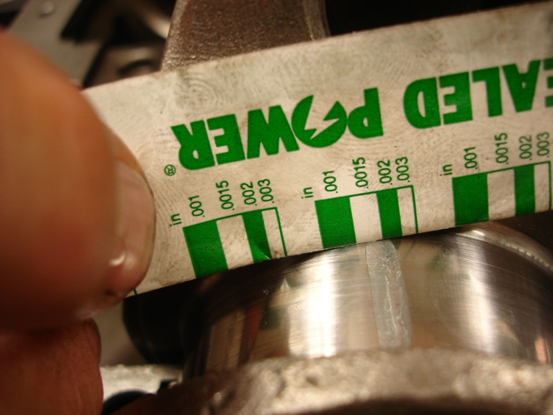
We set the crankshaft in the main bearing saddles for the Plastigage bearing clearance check. The main bearing caps are installed, then torqued to factory specs. The main bearing caps are taken off and the crushed Plastigage is checked against the package that the Plastigage comes in. We had .0015 of clearance, which is very close to like new specifications.
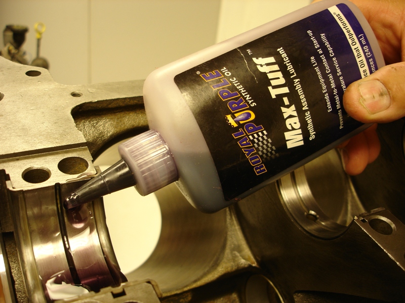
We use brake cleaner to remove the Plastigage from the bearing surfaces. After the clearance check is completed, we apply some engine assembly lube for the final crankshaft installation.
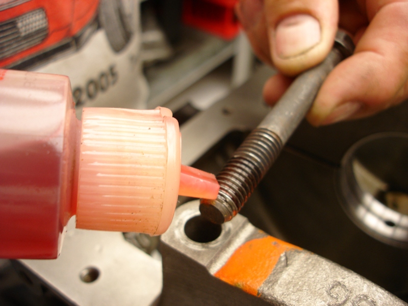
Light engine oil is applied to the bolt threads for correct torque reading.
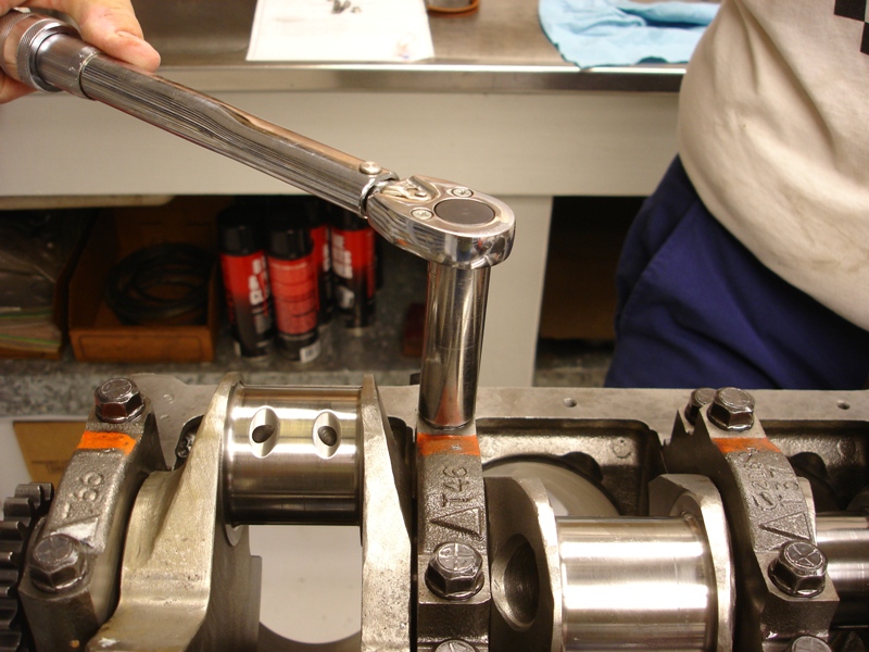
The main bearing bolts are torqued, starting at the center. We first torque the bolts to 50ftlbs, then go over them again, torquing all of the bolts to 80ftlbs.
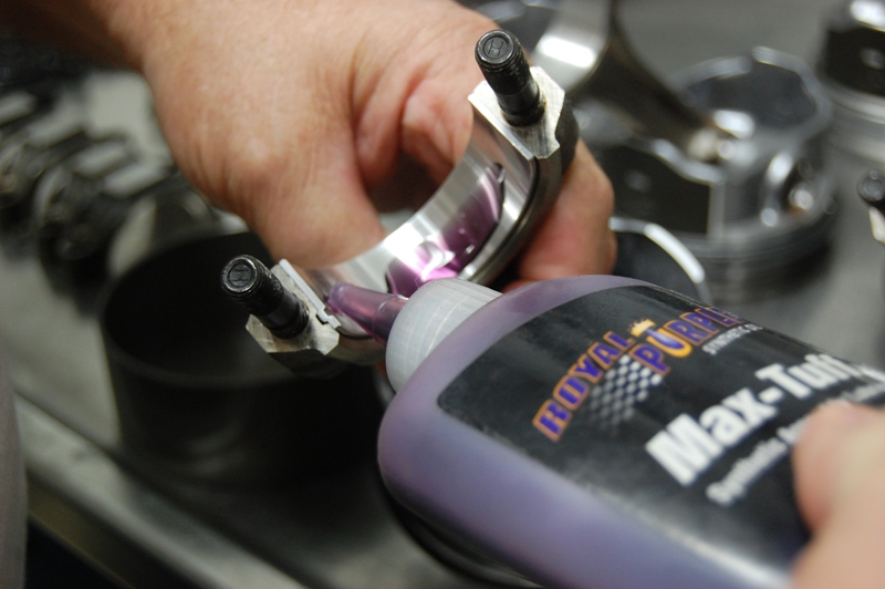
Assembly lube is applied to the connecting rod bearings.
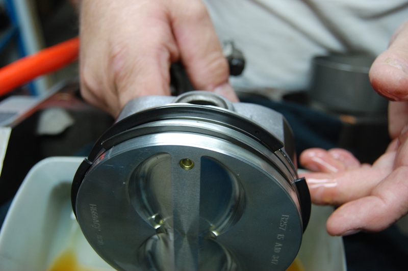
The piston ring end gaps are set apart 120 degrees. We use the front of the piston mark for reference, placing the rings (as shown) on each piston. Each piston is dipped in oil for installation.
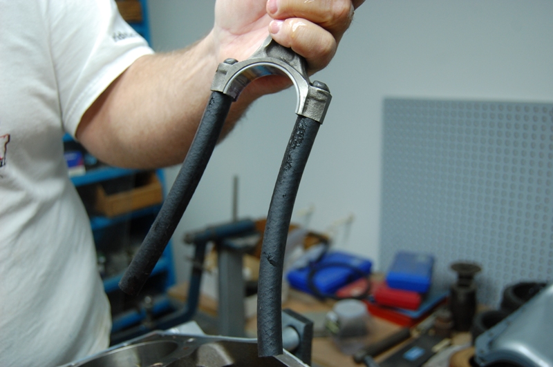
Two pieces of 3/8″ fuel hose placed on the connecting rod bolts will keep them from damaging the crankshaft during piston and rod installation.
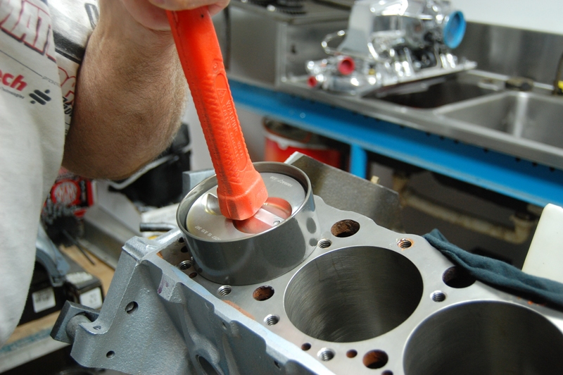
We use these piston ring installation sleeves that are tapered for piston installation. The sleeves allow us to simply push the pistons into the bore without any hammering. The downside is the sleeve only does one size bore, so we have multiple sleeves for the typical bore sizes we service.
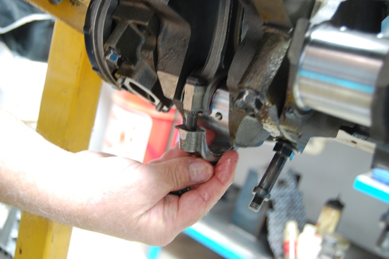
The rod cap is installed and hand-tightened until all the pistons are installed. Each rod bearing lock notch should be on the outside towards the oil pan rail.
Once all the pistons are installed, the engine is turned over and the rod nuts are snugged up. We then rotate the crankshaft a few turns, making sure there are no tight spots.
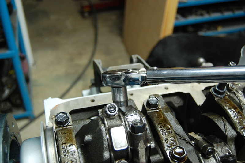
Finally we torque the connecting rod nuts to 45ftlbs, checking them twice just to be safe.
Our new oil pump is installed after pouring some assembly lube into the pump.
The factory oil pan baffle is installed and the oil pump retaining bolt is torqued to 65ftlbs.
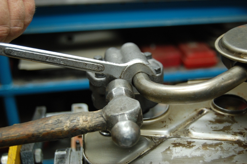
We use this 5/8” open end wrench to tap in the oil pump pick-up tube. This trick works well and keeps from tearing up the tube assembly.
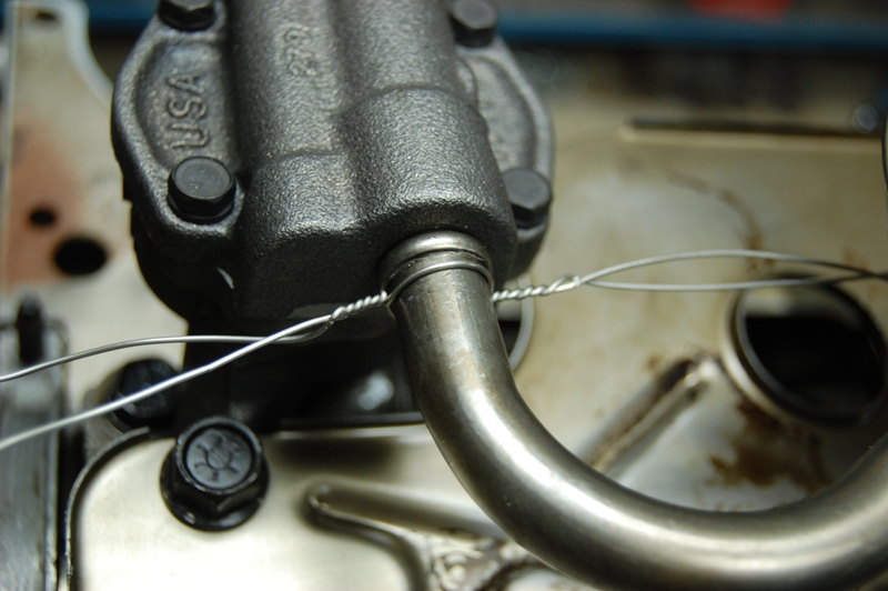
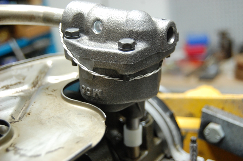
We prefer to secure the oil pump pick-up tube in all of our engine builds. We originally spot welded the tube to the pump. Sometimes the weld would fail and we really did not like the heat applied during the welding. This .035” stainless safety wire is now used for our securing process.
The securing wire goes around the pump, preventing the possibility of the pick-up tube falling out.
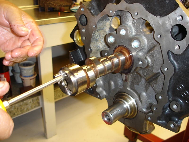
After applying assembly lube, we install our Comp Cams camshaft, using our medium size Philips head screwdriver,. The camshaft has to be picked up off the camshaft bearings as the camshaft is installed. It is very easy to gouge the cam bearings if you are not careful.
This simple camshaft fore-aft retention plate allows the use of roller lifters. The correct 1987-1993 camshaft must be used for this cam retention plate.
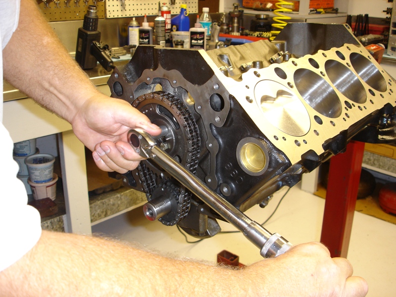
The timing chain and gears are installed and torqued to 20ftlbs. Line the cam and crank gear marks together, cam gear at the bottom crank gear at the top.
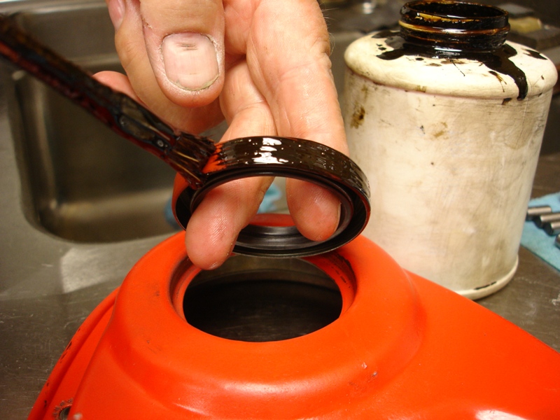
We always use Permatex aviation sealer, applying it around the outer circumference of the seal where it goes into the timing cover.
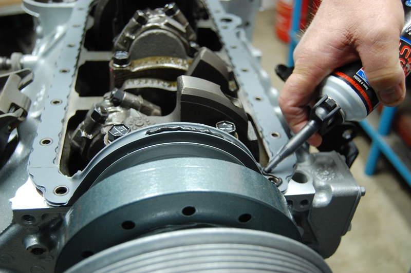
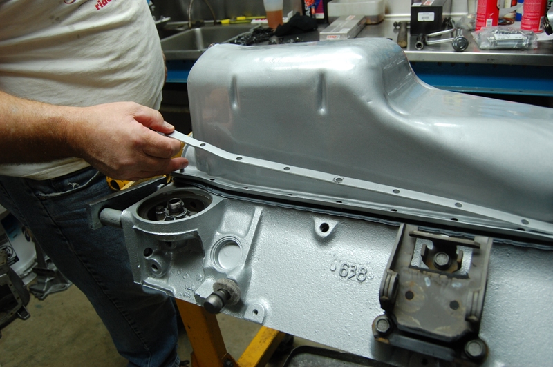
Once the timing cover is installed, the oil pan gasket is next after applying a bead of silicone sealer around the entire perimeter of the engine block.
We apply a 3/16” bead of silicone sealer around the top of the oil pan gasket. Apply just enough to assure the gasket has stuck well to the pan and engine block.
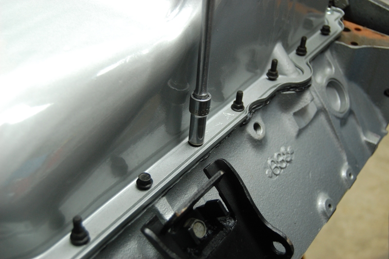
The oil pan is installed with reinforcements. You have about ten minutes on a hot day from the time the first bead is applied to the engine block for the pan gasket. If you wait too long, the silicone sealer will skin over and not stick to any of the parts.
We must keep going, installing all the studs, nuts and screws ASAP so we can tighten down the pan retaining fasteners before the silicone is dry.
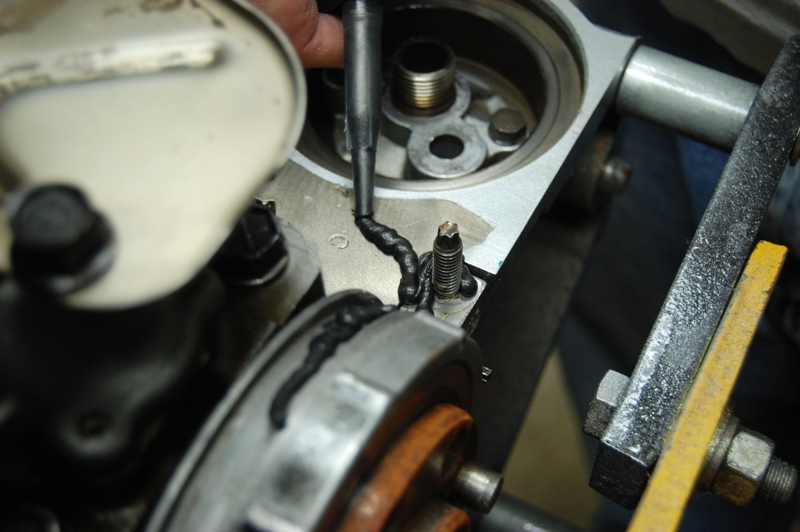
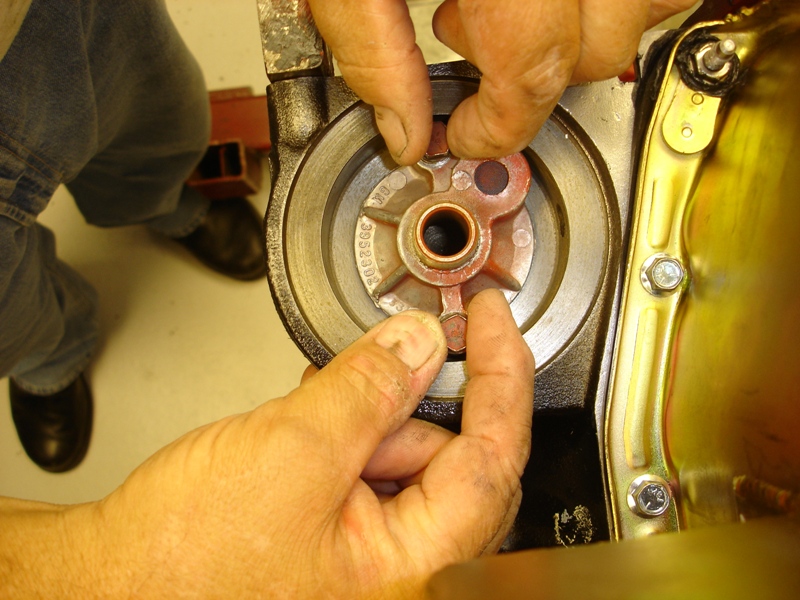
This oil filter screw on stud and relief valve plate is installed with the original reduced hex head fasteners. The plate has a disc that opens up when oil filter flow is reduced, hence the relief valve designation. Make sure there is no trapped dirt or particles under the disc, preventing total closure, or unfiltered oil will make its way into your engine.
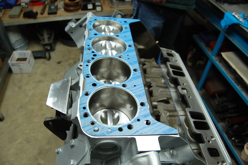
The cylinder head gasket surfaces are wiped off with wax and grease remover or brake cleaner. When placing the cylinder head on the engine block, try to set it in place without gouging the gasket.
The RHS Vortec cylinder heads are being bolted on with Totally Stainless Steel fasteners. Per Totally Stainless Steel, we coated the bolt threads with “never-seize” before installation. We typically use Teflon thread sealer or Permatex Aviation sealer to seal up the bolt threads when using carbon steel bolts.
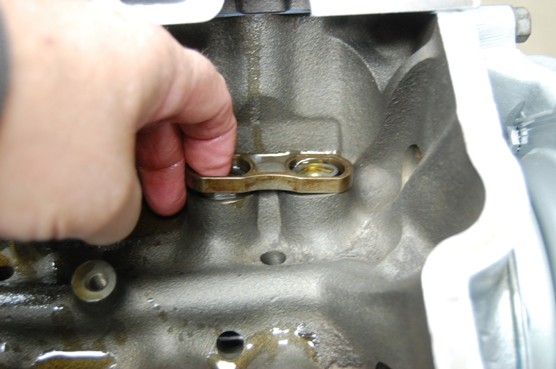
Our pre-soaked roller lifters are installed, then these lifter alignment plates are dropped in place. The lifter alignment plates are held in place with a retainer bolted into the valley with three 1/2″ hex head bolts.
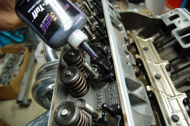
Now we install the Comp Cams pushrod guide plates, after applying Teflon thread sealer to the rocker arm studs. These rocker arm studs screw into open holes in the RHS cylinder head intake runners. Vacuum leaks can occur without thread sealer application.
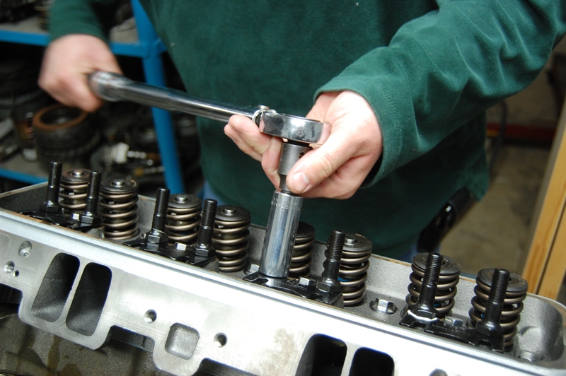
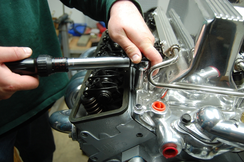
We torque as many fasteners as possible, including the rocker arm studs. The studs are torqued to 50 lbs/ft as soon as possible after installation to keep the thread sealer wet during the process.
The Comp Cams pushrods are installed, then a drop of engine assembly lube is placed on the tip of each pushrod.
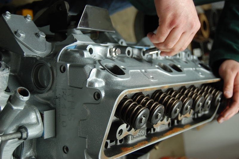
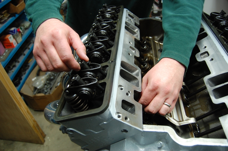
We had to install the valve cover adapters before the rocker arms, after finding that the rocker arms were rubbing on the plates. The rub was due to the use of a gasket under the plate, so we removed the plates and gaskets, and then reassembled the plates with a bead of silicone sealer between the plate and cylinder head. The removal of the gasket allowed enough clearance for the roller rocker arms.
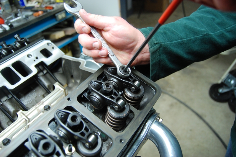
Now the tricky part: adjusting the Comp Cams rocker arms with semi-pumped up hydraulic lifters. Start the adjustment with the cylinder you are adjusting at TDC (Top Dead Center). The trick is finding the point where the clearance is zero so we can apply the required 1-1/2 turns from zero lash. We prefer to do the adjustment with the intake off so we can feel the pushrod drag more easily. We turn the rocker arm adjusting nut clockwise as we rotate the pushrod, feeling for a slight drag. When the lifters are not fully pumped up, it is very easy to tighten the rockers too tight. We are feeling for the point when the pushrod just begins to have a drag during rotation. Once the drag is felt, we turn the rocker arm adjuster nut an additional 1-1/2 turns clockwise.
These positive locking rocker arm nuts come with the Comp Cams Ultra Pro Magnum XD roller rockers.
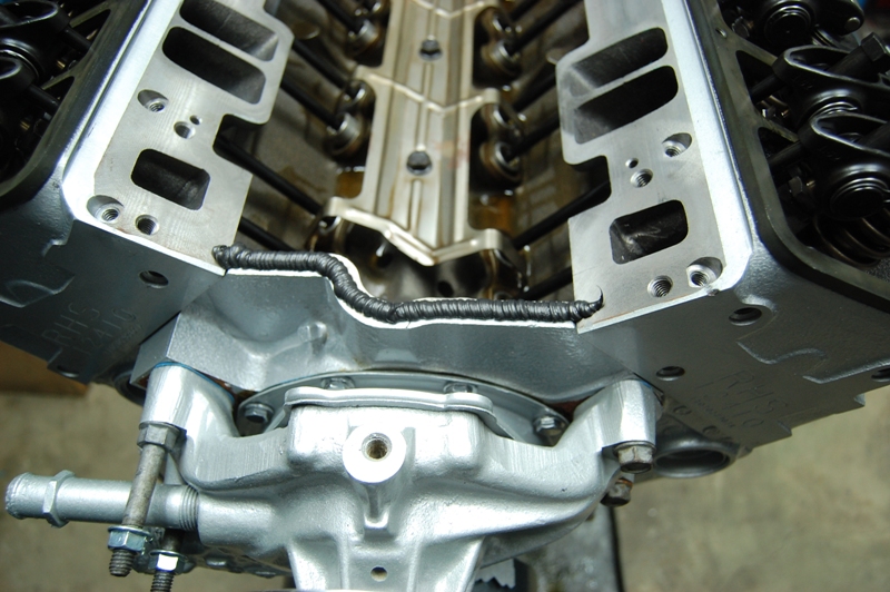
The intake gasket surfaces are cleaned very carefully with brake cleaner or alcohol. Proper cleaning is essential to assure a good bond between the intake manifold and engine block surfaces. Then a bead of hot-oil resistant silicone sealer is run across the front and rear of the engine block.
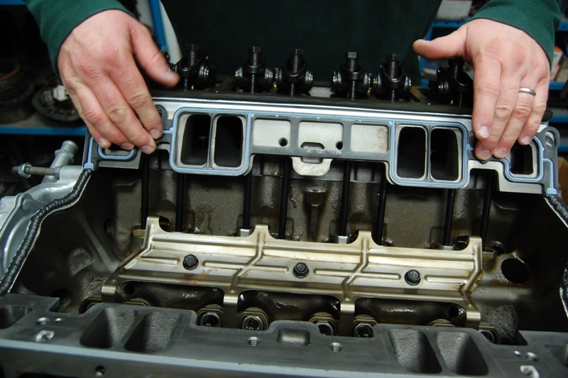
The Vortec intake gaskets are installed next, placing the gasket’s locating studs into the cylinder heads. Remember this is a time sensitive procedure, especially on warm or hot
days. Silicone sealer skins over in a few moments on a very hot day, which means there will be a poor bond between the sealer and surfaces.
We have all the bolts and tools ready for the intake manifold install, so the procedure can be done within 10 minutes. The AZM intake is placed on the RHS cylinder heads, watching the intake bolt holes for alignment. We try to avoid moving the intake manifold around much, which can compromise the silicone sealer.
Jerry spent quite a bit of time putting together the upper engine stainless steel fasteners. All of the upper engine fasteners are polished stainless steel to match the chassis fasteners. The side mounted throttle body will be connected to an original factory equipped fuelie air cleaner.
Here we torque the intake bolts to 20 lbs/ft per AZM specifications. We always go over the intake bolts multiple times to make sure they are torqued properly. The gasket settles into place as you go around tightening the bolts, so it takes a few times to make sure all the bolts are tight.
Tech Notes:
CC Oil Pan
This new oil pan, part number 302298, is available from Corvette Central for the early two piece rear main seal engine used from 1963-1974. The replacement oil pan is a correct fit piece, requiring part number 302125 oil pump pick-up tube.
Our next phase will cover the transmission and differential. Although we did not cover the camshaft selection, it will be discussed in the next installment. Camshaft selection is very important, requiring vehicle weight, usage, transmission and differential gearing information to determine the best choice. Stay tuned for all the data that we used for this important decision, including the driveline gear choices.
If you get a chance, come out and see Split Mod’s Chassis at the Corvette Expo in Houston, Texas on February 11-12, 2012. Hope to see you there!
Story and photos courtesy Chris Petris











Two questions: Where’s the oil fill cap and, more importantly, how do you intend to ventilate the crankcase? 1968 and later SBCs have no vent hole at the back of the block and, 69 and later intakes have no oil fill tube at the front of the intake. This fact makes using ‘no hole’ valve covers impossible on a late model small blocks. If you know of a ‘workaround’ for this dilemma, I’d like to hear about it.