1965-1982 Corvette disc brake systems were a major technological advancement at their onset. The C2/C3 Corvette design utilized “fixed” disc brake calipers. This same “fixed” design disc brake caliper was used on GMs other than Corvette high performance vehicle line-up in limited quantities during 1965-1968. When disc brakes became commonplace in 1969, “floating disc brake calipers” were used. Floating calipers slide on a ways system, repositioning the caliper as the disc pad wears. This sliding or floating caliper proved to be a good thing, allowing for discrepancies that the fixed caliper would not compensate for. From 1969 on, the majority of vehicle manufacturers used floating disc brake calipers for easy serviceability, while GM utilized the early style fixed calipers on the Corvette until 1982. There was a J56 brake option for the fixed disc brake calipers consisting of heavy duty semi-metallic pads and two pins to retain the pads. In addition Inconel steel reinforcements were placed on the caliper mounts to the spindle to prevent caliper flexing under severe braking. Good stuff but hard on brake rotors you can expect to replace more rotors than the unique J56 disc brake pads. Another downside was the J56 brake option required heat to build before they worked well and with less effort.
Rotor run-out (parallelism) issues have plagued fixed disc brake calipers from the beginning. Floating calipers are not as susceptible to rotor run-out concerns. The caliper simply repositions itself for the run-out discrepancies on the slides. Disc brake pad wear is usually more even as the slide lets the caliper move around. Floating calipers typically have one large piston squeezing the assembly, forcing the disc pad against one side of the rotor while the outer disc pad is held stationary in the assembly.
Why would GM decide to keep this early system for so many years when floating calipers were more popular? Possibly for better braking under extreme conditions, as the fixed calipers apply equal pressure to both sides of the rotor with multiple pistons. Lower production numbers may have also factored into the equation. GM kept the fixed calipers around for seventeen years of production. That means a whole lot of original equipment Corvette fixed calipers are out there.
A common issue with the early heavy cast iron calipers is piston seal failure. Low drag lip-type piston seals were used to seal the piston to the bore. Two major concerns with the design were discovered. One was the caliper pistons moved like little engine pistons if the rotor run-out was not perfectly true. This constant caliper piston motion created two problems, air infiltration and seal wear. The second issue with the cast iron bore was the outer seal surface. Once water caused the iron to rust, the seals were torn, causing leaks. Worse yet, the brake caliper housing seal surfaces would become pitted from corrosion. The only fix for the corroded housings was to find another piston housing or stainless steel inserts. An industry was formed to install stainless steel sleeves into the original cast iron caliper housings.
Which are better, fixed or floating calipers?
Floating calipers seal against the caliper piston surface. When floating calipers corrode, the housing can be cleaned up and the corroded pistons can be replaced. Maintaining floating calipers is fairly simple and not very costly. Fixed calipers do have a place though. High end disc brake systems go back to the original concept of fixed calipers with multiple pistons. Race applications use the fixed caliper design because of the extreme braking forces available. Additionally, floating calipers could conceivably be torn from their mounting points under race conditions. The downside is brake rotor run-out should be maintained for the best possible braking. Rotor run-out can press the caliper pistons into their bores, which will create a spongy brake pedal feel as the slack must be taken up before the brakes apply.
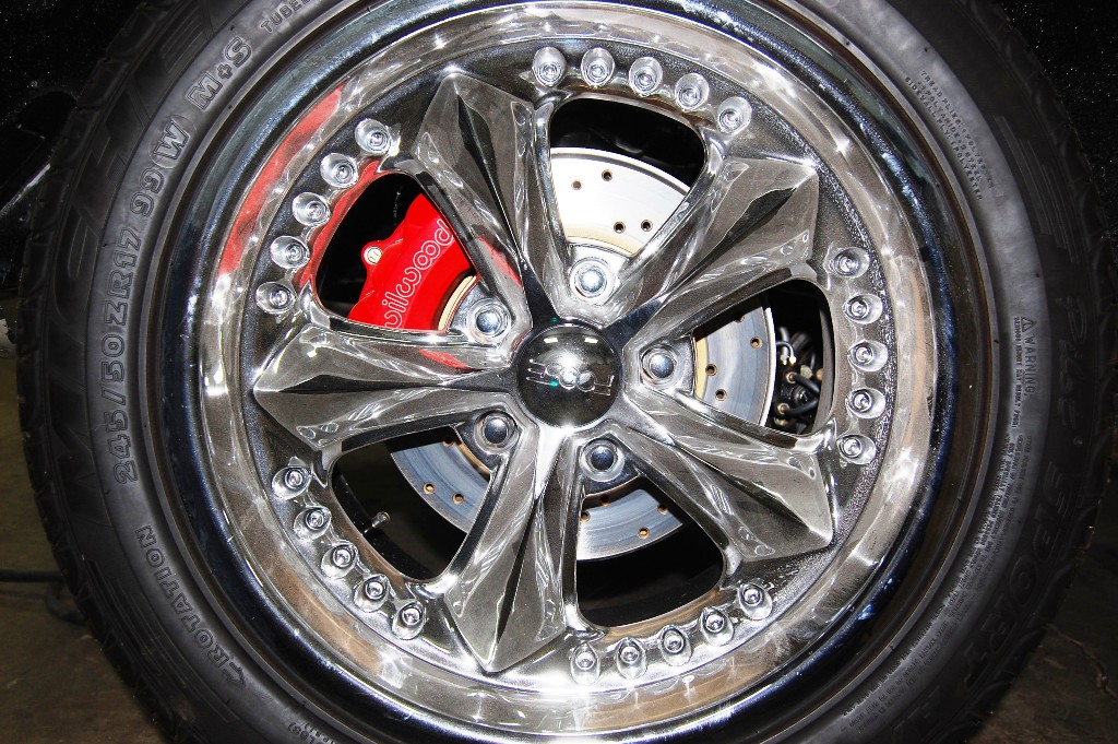
Wilwood has taken the original design and modified it for dependable braking under extreme pressure, as well as eliminated the seal failure problem by using competition-style high temperature piston seals. Original equipment caliper piston sizes have been maintained to keep brake balance while using the OE brake booster and proportioning valve. These lightweight aluminum calipers mount in the stock location for quick installation. Shedding unsprung weight at the wheel is always a good idea for better handling and control. The factory calipers weighed a bit over 13 pounds each. The Wilwood D8-4, Corvette Central part 192280, weighs about 5.75 lbs dry, dropping around 28 lbs overall. The Wilwood D8-4 caliper will also fit under a stock size wheel on a factory diameter rotor. Powder coated and polished calipers have an additional charge but they look great. Another nice feature is you can use a factory set of disc pads. Front and rear caliper kits come complete with correct fit stainless steel braided hoses, pads and installation hardware.
Brake fluid
The DOT designation stands for boiling point of brake fluid, wet or dry. “Wet” includes water that has dispersed throughout the brake system. Glycol fluids DOT 3 and 4 are hygroscopic, absorbing moisture throughout the life of the fluid. The absorbed moisture lowers the brake fluid boiling point causing brake fade. Wilwood and many other brake suppliers recommend annual brake fluid flushing. We recommend a complete brake system flushing every two years for street driven Corvettes. Track events where the brakes are used under harsh high heat conditions should have the fluid changed after the event.
Wilwood does not recommend using DOT 5 fluid in any racing applications. DOT 5 fluid does not absorb water. The resulting moisture beads move through the brake system and can cause vapor lock and brake failure. Additionally, DOT 5 fluid is highly compressible due to aeration and foaming under normal braking conditions, providing a spongy brake feel.
It has been said that DOT 5 fluid expands and causes brake systems to lock up under hard braking conditions. As you undoubtedly remember from science class, all fluids expand as temperature rises. DOT 5 fluid is perfect for Non-ABS brake systems that are driven infrequently. My personal big block early Corvette has DOT 5 in the reservoir and when it gets driven, it gets driven hard. I have yet to have any complaints about pedal feel (spongy) or locked-up brakes. In spite of the fact it has DOT 5 fluid in the reservoir, it still gets flushed every two years.
As a side note, the US Armed Forces has used DOT 5 silicone fluid since the 1990’s in all of their vehicles without ABS braking systems. A Humvee rolling through the desert in the Middle East probably would be considered severe duty in all categories.
Brake rotor inspection
Checking rotor run-out is not common for brake shops that frequently deal with floating calipers, but inspection and adjustment assures long caliper and brake pad life. Rotor run-out is not necessarily caused by a rotor machining error. Any wheel hub run-out carries over to the rotor, where its large diameter exacerbates the situation. In other words, having the rotors machined will not guarantee correct rotor run-out readings. Likewise, new rotors can have run-out issues because of hub run-out problems. Worn, loose wheel bearings will make it very difficult to inspect rotors correctly. If the front or rear wheel bearings are loose, fix them before rotor inspection. From the beginning, GM has specified that .004” of rotor run-out is the maximum allowed. Wilwood recommends .005-.008” maximum run-out for their rotors. In our shop, we will continue to keep the rotor run-out within GM specifications for long brake caliper life. Follow along as we show you how we check run-out and the necessary remedies for incorrect run-out.
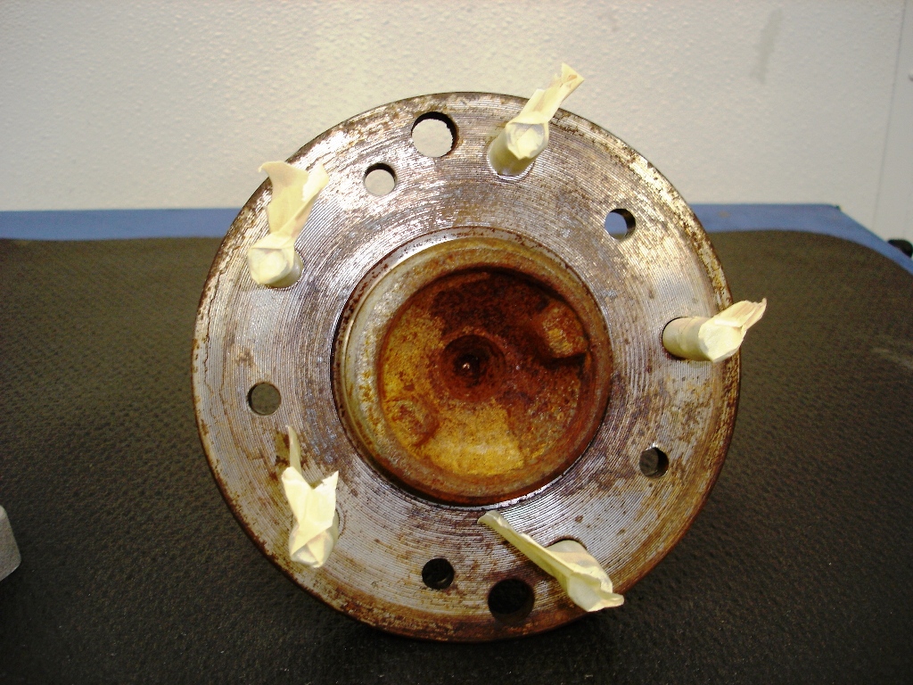
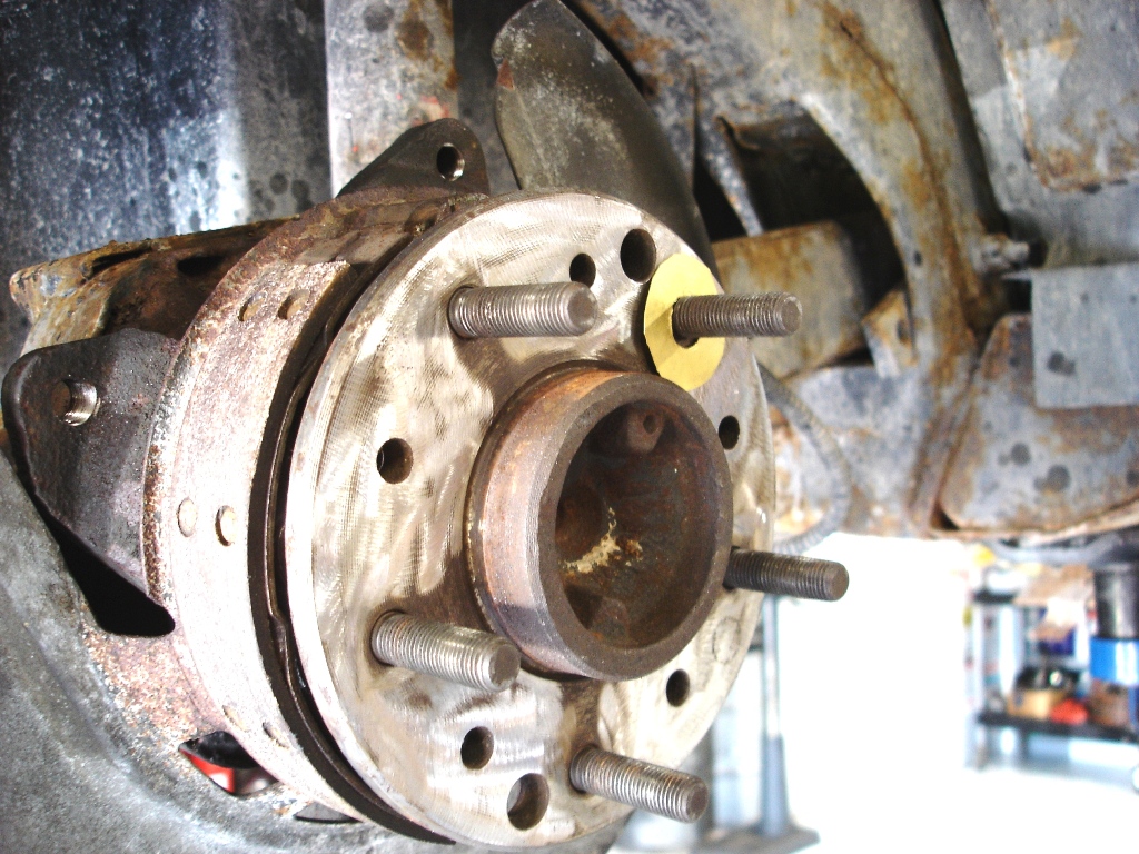
This rear wheel spindle hub is from a ‘77 that was getting a spindle bearing replacement. The two large holes in the flange with the wheel studs are for emergency brake shoe adjustment. The five small holes are from rivets that were drilled out for rotor removal. When the rivets are drilled out, the remaining pieces are knocked out with a punch. The rivet holes become enlarged between drilling and the punching. As the holes become enlarged, they raise up the surrounding metal, preventing a flat surface for the rotor to sit against. Clean the flat surfaces and make sure any raised areas are reduced with a grinder if necessary.
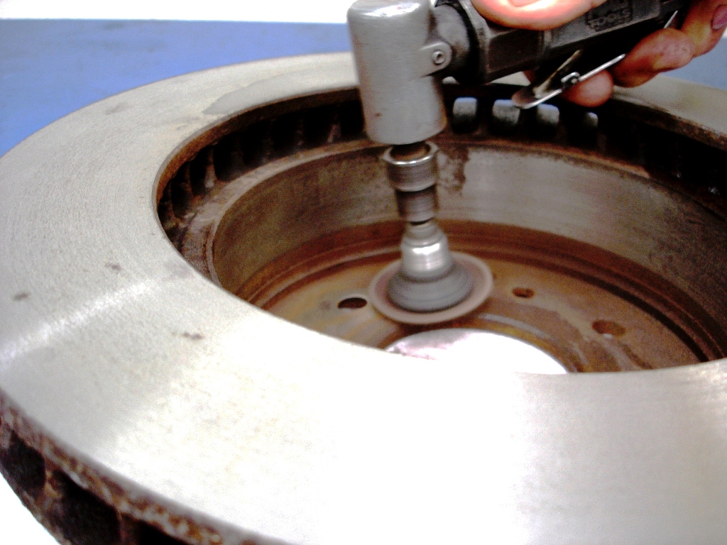
A high speed angle grinder does a great job of cleaning years of build-up of rust and corrosion. Red Scotch-Brite discs work well for general cleaning. 36 grit sanding discs work better on really rough areas. This same high speed grinder with 36 grit disc also does a good job of reducing the high spots on the spindle.
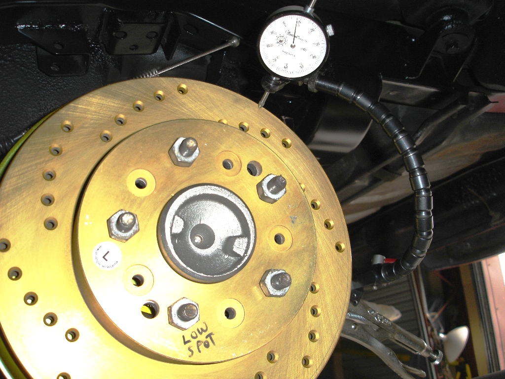
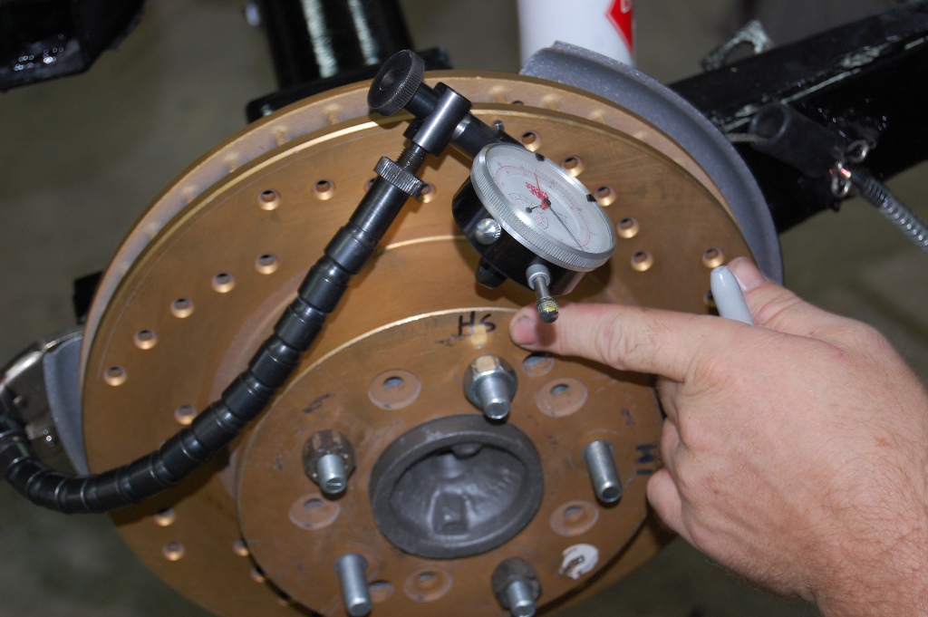
Our flexible mount dial indicator is set-up for run-out inspection. The dial indicator is set to zero and then the rotor is rotated one revolution to determine run-out measurement. Our .008” run-out is twice the factory recommendation. Mark the low spot at the opposite end to remember where the shim should be placed. Exercise caution to determine the exact high spot in order to can place a shim 180 degrees across.
The hub is cleaned up and the shim is installed, ready for the first attempt at run-out correction. Use brass shim stock from your local hardware store. .005” is the thinnest brass shim stock we could find. Cut the shim with metal snips and then use a gasket punch to put a ½” hole in the center. Drilling .005” material is not easy; it bundles up as soon as a drill touches it.
The rotor is installed and checked again for a maximum .004” run-out. Remember that placing a .005” shim on one side will raise the side the shim was installed on, but also drop the opposite side as the rotor gets closer to parallel. It may be necessary to move the shim to an adjacent stud to get the correct maximum .004” run-out reading. Always mark the high and low spots and where the shim is to be installed.
Before installing any caliper, run a 7/16-20 bit through the threads. Apply light oil to the thread tap to prevent a sticking or breaking. The threads are always full of corrosion, preventing an improper torque reading. The rear calipers are bolted to the threaded caliper mount. Front calipers are threaded themselves with the bolt going through the caliper mount. No matter who manufactured or remanufactured the caliper, always run the 7/16-20 thread tap through the front calipers. Many times the threads are not as clean as they should be.
Something else to watch for on the front and back caliper mounting is bolt length. Improper length bolts can chew into the rotors or rip the threads out. Standard bolt lengths are in quarter inch increments. The proper length bolt for the caliper mounting is 1-1/8 with a 7/16-20 thread. Use the next available length of 1-1/4 long with a lock washer and SAE flat washer. All bolts and washers are grade 8 quality. The SAE designation on the flat washer means it fits tighter on the bolt threads. USS flat washers are loose on the bolt threads. For example, a 3/8 USS washer will typically fit a 7/16 bolt.
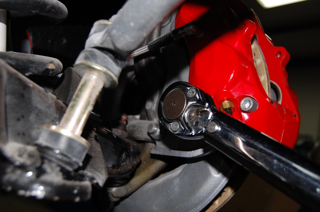
After our caliper bolts are installed with a drop of blue Loctite, they are torqued to 65 lbs/ft. Always torque the caliper bolts to make sure the threads are in good shape and the caliper is properly tightened.
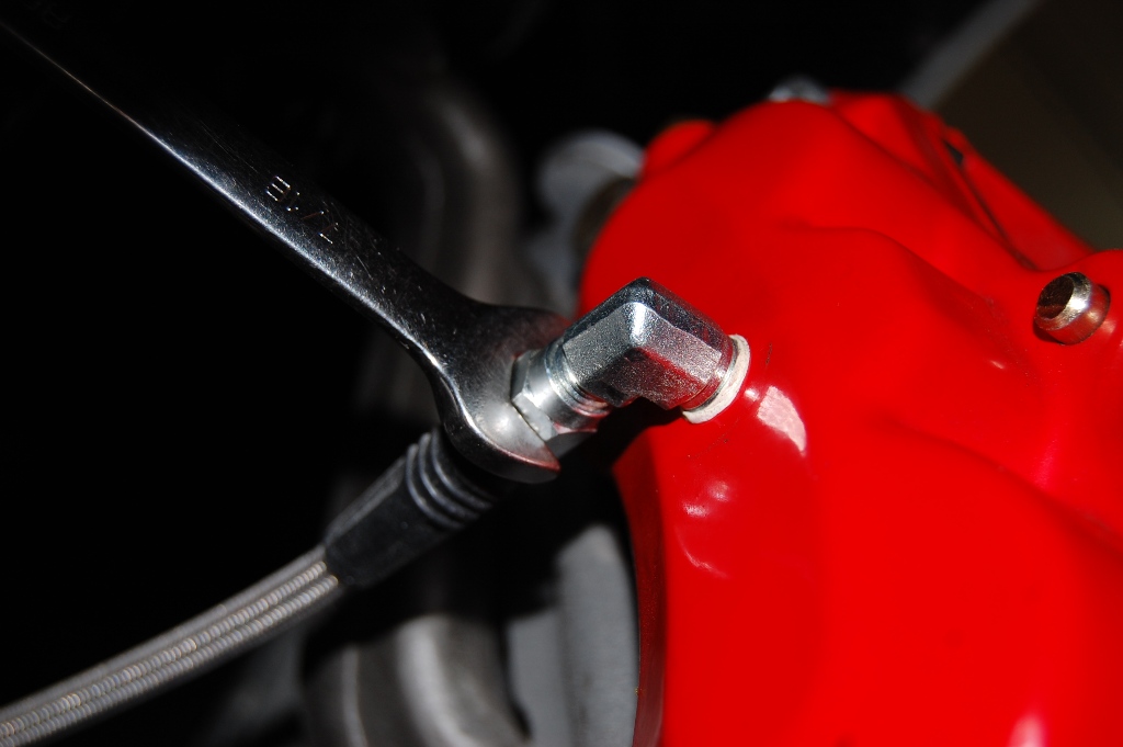
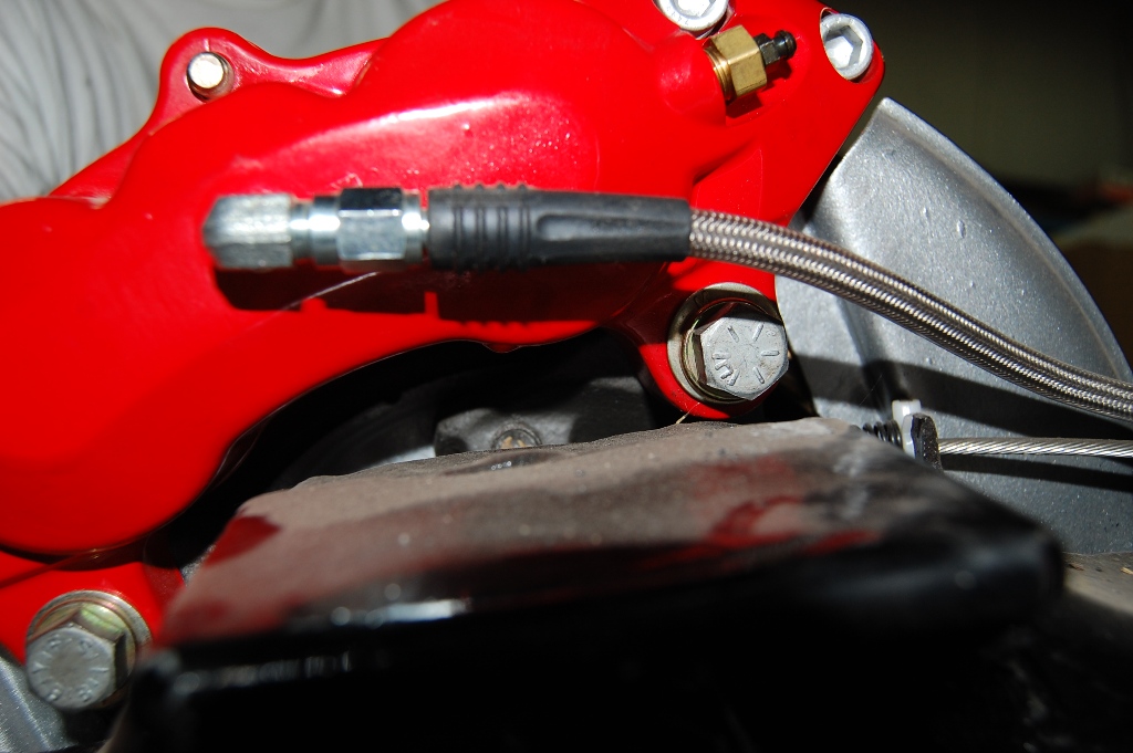
Wilwood supplies all the fittings and hoses for the front caliper installation. The 90° fitting has a light coat of Teflon thread sealant applied to aid in sealing. Apply the sealer after the first two threads on the fitting to avoid contaminating the fluid during installation. We have found that when the fitting is clocked horizontally with the frame, it provides for optimal hose movement during turns.
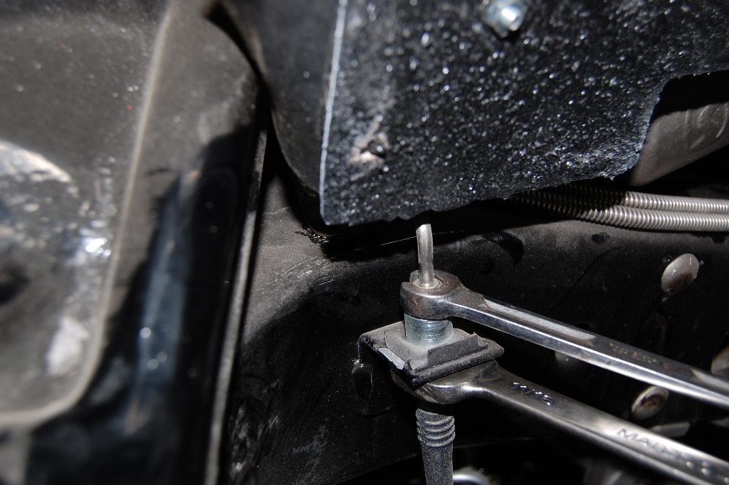
At the frame connection, we installed the hose adapter fitting on the hose, followed by the brake line to the adapter fitting. Hold onto the adapter fitting when tightening the line and hose to avoid twisting the hose. Always use a line wrench on the line nut to avoid damaging the fragile nut. We used stainless steel lines from Corvette Central on this project that required additional tightening to avoid leakage. The stainless material is harder and takes more effort during tightening to seat the lines.
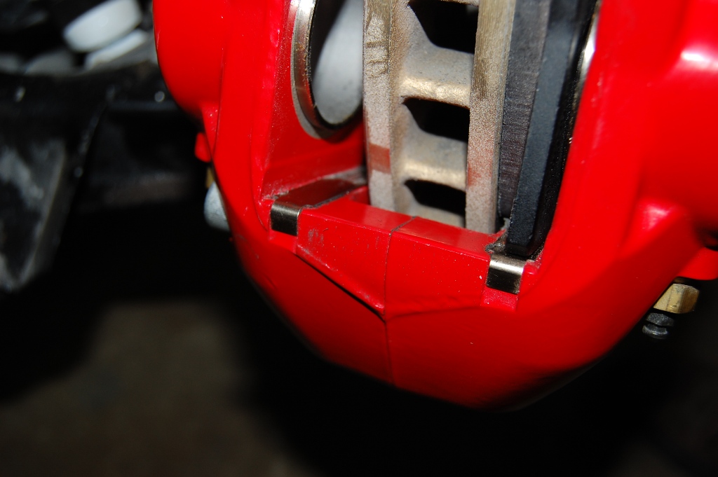
Wilwood uses these stainless strips to keep the disc pads from rattling. The strips also keep the steel disc pad backing plates from chewing up the aluminum caliper. Make sure these are in place before installing the pads.
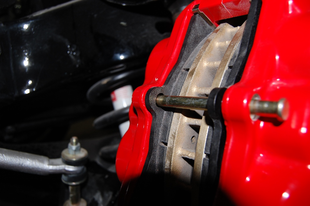
Install three lug nuts on the rotors to keep them sitting flat against the hub during pad installation. The Wilwood-supplied pads are slipped in place, followed by installation of the pad retaining pin. The pads should slip easily in place between the caliper pistons and rotor. In some situations, shims may be required between the caliper and the mounting pad to center the rotor in the caliper.
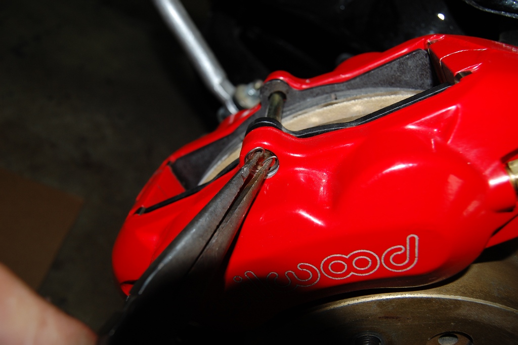
We are just about finished with the front caliper installation after this pad pin retaining clip is installed. Make sure the clip is in the groove along the circumference.
On the rear caliper, we used our grade eight 7/16-20 x 1-1/4 long bolts with the flat and lock washers. Note the orientation of the calipers 90° fitting (perpendicular to the trailing arm top surface).
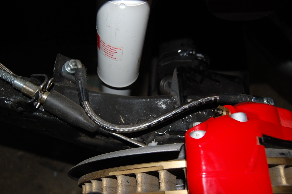
Wilwood supplies this stainless steel braided hose to replace the original hard line. We found this hose orientation worked best for clearance purposes.

Wilwood does not supply this flex hose from the original brass brake tee to the trailing arm. We used a set of Corvette Central stainless steel braided hoses, part number 193050, for our installation. Like the front, you need to hold onto the adapter fitting during tightening and watch for hose twist.
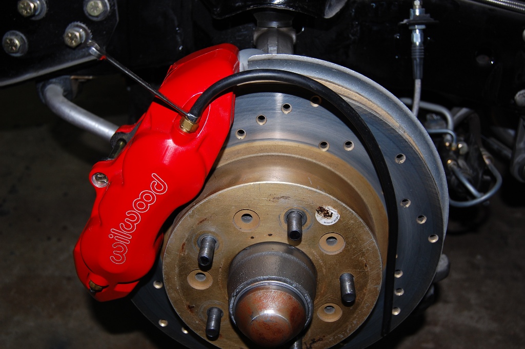
The calipers and rotor stay fluid free with this piece of vacuum hose installed for a fluid diverter. Wilwood uses quarter inch hex head bleeder screws that can be tight. Use a six point wrench for a good grip.
BRAKE BLEEDING TIP:
1965-1982 Corvette brake bleeding can be difficult. We use a pressurized system in our shop. The pressure pot is similar to a garden sprayer that holds brake fluid. An adapter is placed on the master cylinder and then the connecting hose is attached. Fill the tank with the fluid of your choice. The pump then pressurizes the tank. When there is about 20 PSI in the tank, open the valve at the master cylinder adapter to let fluid flow. Then the brakes are bled in the traditional manner, starting at the farthest point (passenger side rear) then driver side rear, right front and left front. It is not necessary to have someone pump the brake pedal. You will be able to notice any fluid leaks as soon as the fluid is flowing from the pressure pot. When you have the entire system in pieces, small leaks are possible from not tightening a fitting properly. The entire system is available through Corvette Central, part number 191119.
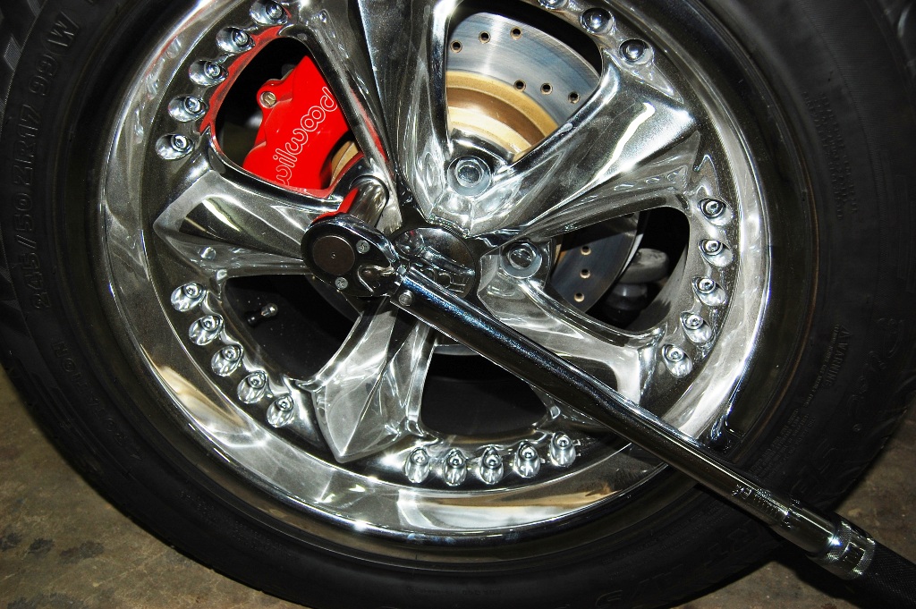
Torqueing the lug nuts is a must, but impact wrenches and big four way wrenches can warp rotors. Slamming the lug nut down with a large impact wrench creates misshapen rotors, ruining your hard work perfecting the run-out in seconds. Torque the wheels to 95 lbs/ft in a star pattern for best results.
BREAK-IN PROCEDURES
The bedding process is the final “heat cure” for the pads. This bedding cure differs from an oven heat cure because oven heat cure does not include the pressure, torque, and elevated surface temperatures that are necessary to properly condition the pad for service. As it is with the rotors, new pads must be gradually brought up to temperature and then slowly cooled. If the pads are put into hard service right from the start, damage from fractures or accelerated deterioration due to extreme temperature variations between the surface and the body of the pad can occur. Overall poor performance with the potential for rotor damage are often the results.
Disc Pad Bedding:
Once the brake system has been tested for good brake pedal feel and no apparent leaks, follow the steps below for bedding of all pad materials and rotors.
- Begin with a series of eight to ten light stops from approximately 30 MPH down to 15 MPH, allowing 20-30 seconds for pad cooling between each stop.
- Next, a series of eight to ten moderate stops from around 45 MPH down to 30 MPH allowing a 20-30 second pad cool down period between each stop.
- Finish off with a series of eight to ten hard stops from 55-65 MPH down to 25 MPH, allowing 20-30 seconds of pad cool down time between each stop.
- The final step is to drive at moderate cruising speed, with the least amount of brake contact possible, until most of the heat has dissipated from the brakes. Avoid sitting stopped with the brake pedal depressed to hold the car in place during this time. Park the vehicle and allow the brakes to cool to ambient air temperature.
Story and photos courtesy Chris Petris


Will the Wilwood full caliper set work with my original rotors on my ’81 Corvette or do I need new rotors?
thank you,
I have replaced the complete brake system and I still have a full brake pedal until I start the engine, then pedal goes to the floor
This is definitely something a professional brake shop should look at. If all of the parts are new and operating, the system needs to be bled again and the vacuum source needs to be checked. It is possible that there is a faulty part, but no way to be sure until a brake shop has gone through it.
Great article, looks well worth the grand to upgrade.
I own a 98 C5, 42000 miles, the emergency brake does not engage, the handle pulls up fully with no tension. the the brakes seem fine, what could cause this problem?
I would recommend following the cable and check for any issues. If you still can’t find anything then the next step would be having a certified technician take a look at the car.
I own a 1982 collectors edition corvette with 41,000 miles on it. I have driven it 2-3 times in the last 7 years and noticed recently the calipers are leaking. Easy solution replace both calipers or repair with caliper kit? Opinions appreciated.
We offer New and Rebuilt calipers for 1982. Knowing that the car has sat for that long it may be a good idea to replace the calipers. Here is a link to the calipers we offer https://https://www.corvettecentral.com/search?CurrentSearchCategoryId=&q=caliper&Years=1982
Can I use a front spindle disk brake system off a corvette for brake conversion on my 1964 Chevy impala?
Unfortunately we only specialize in Corvettes.
Disc brakes off a 65-82 Corvette will fit your 64 Impala and clear some 15 inch steel wheels, but if you find any rubbing then you’ll need to add a spacer.