We left off with the Project Split Mod body on a dolly for transport to the body shop and a severely rusted frame. Much has happened since our kick-off of the Project. The body was dropped off at the body shop for all the necessary repairs and painting. We now have a rolling chassis ready for body installation. We mentioned all the severe rust the frame and chassis pieces had endured. It just made good sense to hang new and or remanufactured parts on our Impact Restorations supplied 1963 frame. Why fight the really difficult to remove original parts off the crusty original frame? The original rusty parts will be used for documenting the correct parts.
Corvette Central sells parts as we are well aware of. Researching and developing the parts sold is what sets them apart. Many hours are spent making sure that the parts sold really work. Whether the part is for an early or late, Corvette testing has been performed to assure quality. This takes constant scrutiny of all the parts that pass through to the consumer. Rest assured that Corvette Central is concerned that the parts you receive are built to perform. This is a huge part of the “Split Mod” project utilizing pieces available through Corvette Central. The project is a testbed for many of the products for fitment and reliability. We are providing feedback to Corvette Central as the project comes together to improve parts supplied to the customer.
Corvettes at Carlisle was coming up within a month, pushing us to assemble the chassis for display at the show. As our parcel delivery service was busy bringing in all the necessary pieces for our frame assembly, we were checking the fit of the pieces onto the primed frame. A lesson learned is: to fit the pieces before the final painting. No matter how careful you are, it makes sense to trial fit pieces. Once we felt comfortable with the assembly of our chassis components, it was time to paint the myriad of pieces. We loaded up the truck and trailer with “Split Mod’s” parts for painting.
A trip over to Elite Custom Paint and Body (Lafayette, Georgia) was next. Elite set up the Corvette’s frame on their rotisserie for some smoothing. Painting all those parts was going to be interesting, as suspending the majority of them overhead for paint application was the plan. We explained our two-tone paint plan to Bryan at Elite. We wanted dark gray for the frame and major suspension components. Silver would be used to coat the contrasting smaller pieces that attach to the frame. Urethane paint with hardener would be applied to approximately 100 parts in their paint booth.
While Elite was painting the chassis, we were planning and forecasting the necessary parts. This is a necessary evil that requires constant upkeep to prevent loss of time. Elite came through in record time, leaving us a week to assemble our rolling chassis. Now it was crunch time: could we assemble the complete rolling chassis in the coming week? Did we select the correct parts? We would know within the coming days.
Our plan of attack started with assembling the chassis sub-assemblies. Our trailing arms consisted of many new pieces that required assembly. The differential center section was a rebuilt unit with a new cover. With the sub-assemblies put together, we can hang them on the frame. We had to exercise caution here, as everywhere we look, paint is ready to be chipped off with one slip of the wrench.
Photos of assembling the trailing arms
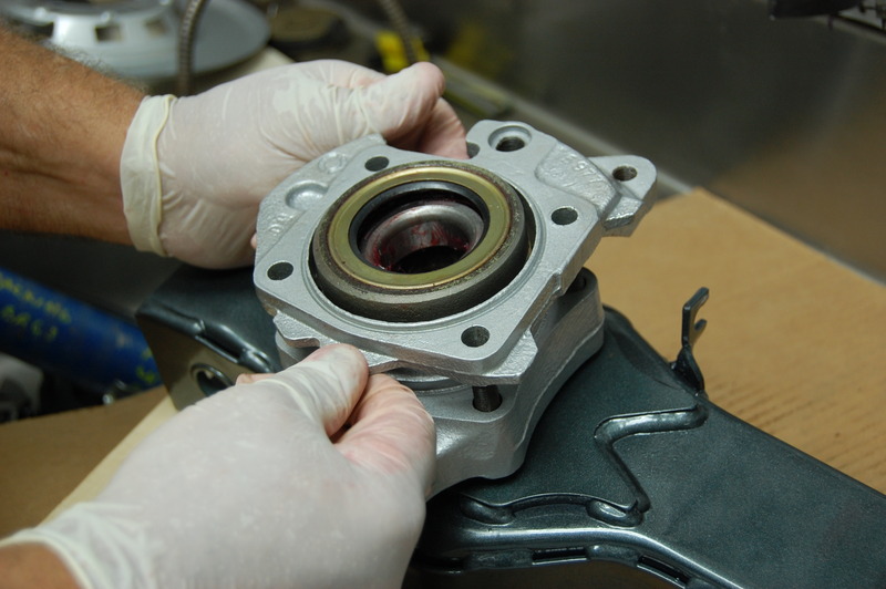
Watch the orientation of the lower shock mount in the rear spindle housing. The flat in the spindle housing must be facing towards the rear of the car. If you mix them up, the entire bearing assembly must come apart and be switched to the other side. Pictured is the passenger side.
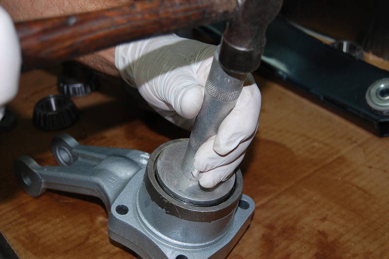
Fresh bearing races are being installed into the spindle housing assembly. Make sure the bearings are installed squarely and bottom out completely.
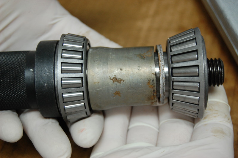
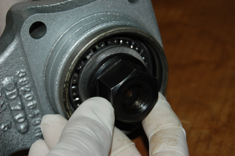
This is where the Corvette Central part number 582418 special bearing preload tool is used to determine the correct shim. Without this tool, the bearing assembly may require multiple efforts to get the clearances correct. It is very difficult to remove the rear wheel bearings without damage. Invariably, they require replacement with each attempt. This tool makes it a “once and done” event.
This is the same part number 582418 bearing tool in the spindle housing prepping for the preload check. Try to keep the bearing clearance in the .000 – .003 range. The perfect scenario is a slight drag on the bearing set-up tool when rotating.
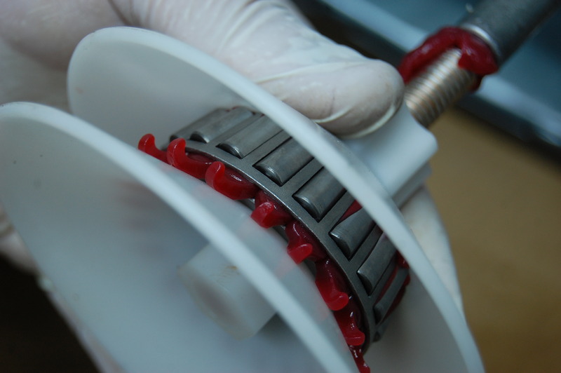
This handy bearing packer keeps hands a little cleaner while forcing the grease deeply into the bearing. The grease must be forced out between the bearing rollers and cage for proper lubrication.
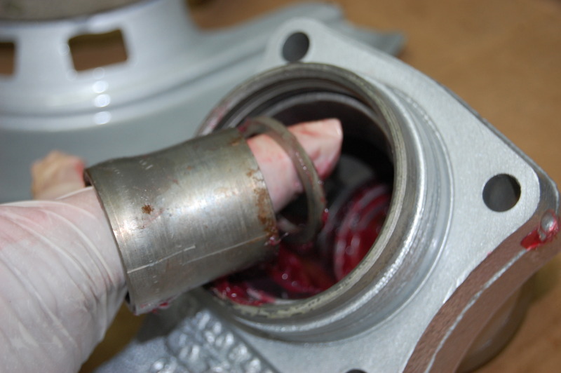
We have installed the front grease seal, and now we are placing the bearing sleeve and proper shim in the spindle housing. Note the taper of the sleeve is larger towards the top. The larger side of the sleeve goes towards the outside (wheel side) of the spindle housing. If your spindle sleeve or shims are in bad shape, Corvette Central has part number 582021 sleeve and shim kit available. It is possible that the original shims may not work. In this case, new shims will be required.
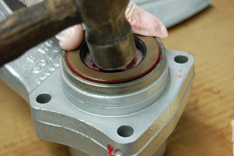
A new seal from our Corvette Central part number 582018 bearing and seal kit is installed.
Lube the brake adjuster with an anti-seizing compound.
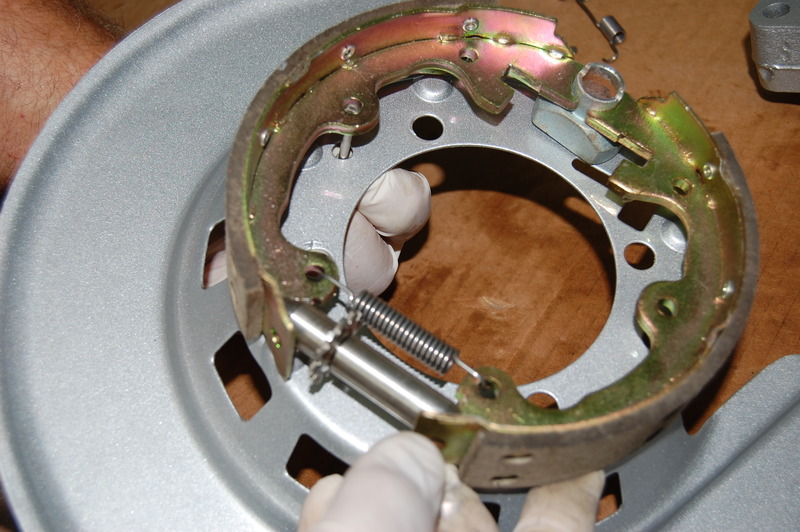
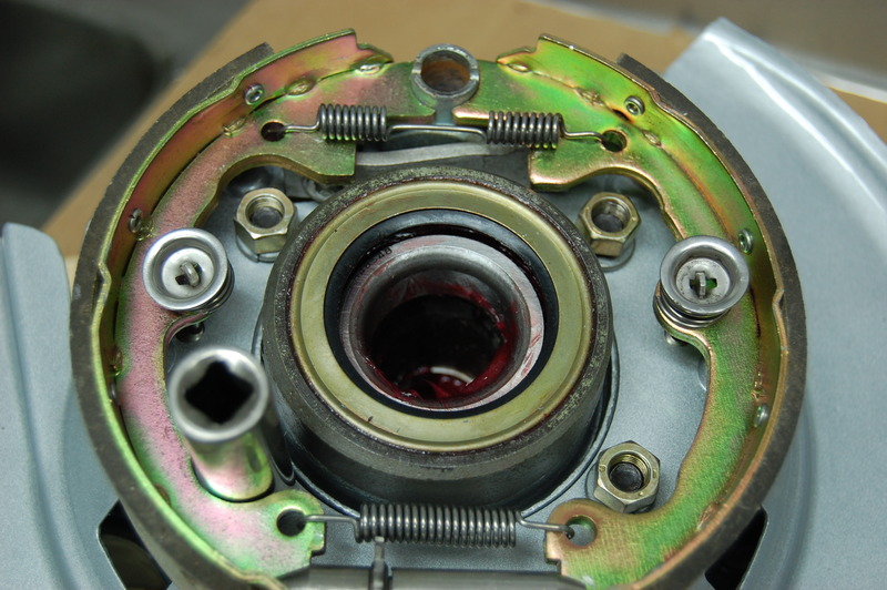
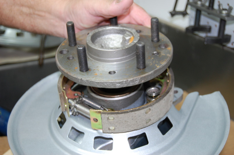
This is by far the easiest way to install the emergency brake shoes. Once the axle is installed, and the entire assembly is finished, it is very difficult to work in this area. We installed Corvette Central part number 193135 stainless steel hardware kit to assure the long life of the E-brake components.
Before our E-brake assembly (with backing plate) is installed, we set our caliper mounting plate in place. We always chase the caliper mount threaded holes with a 7/16-14 thread tap before installation.
Now the E-brake assembly is mounted to part number 582032 (left or right) backing plate. We use new grade 8 3/8-24 nuts and lock washers on all of our builds.
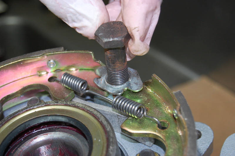
The original 1/2-20 center bolt is installed and torqued to 65 lbs/ft. We also torque the four 3/8 nuts to 45 lbs/ft.
The axle spindle is installed, and the assembly is turned over.
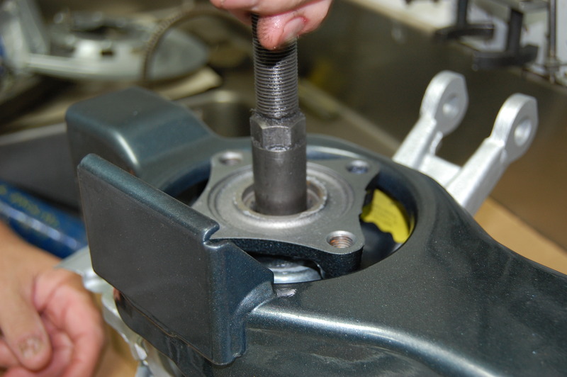
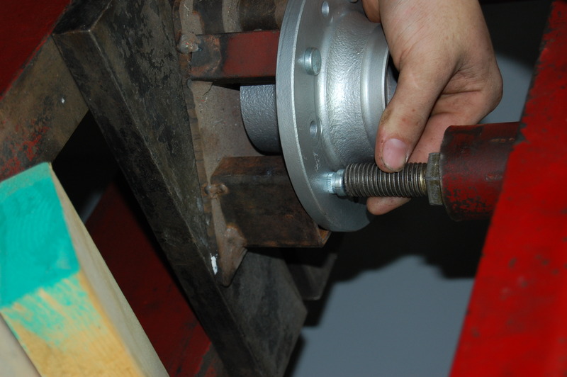
To ease assembly, we are using a Corvette Central part number 582413 rear wheel bearing assembly tool. This nifty tool pulls the spindle into the inner and outer bearing. When you consider the work required, you may opt for the Corvette Central wheel bearing service (number 582192, left or right). The service starts at $235.00, depending on the condition of your components.
Photos of differential cover and beam installation
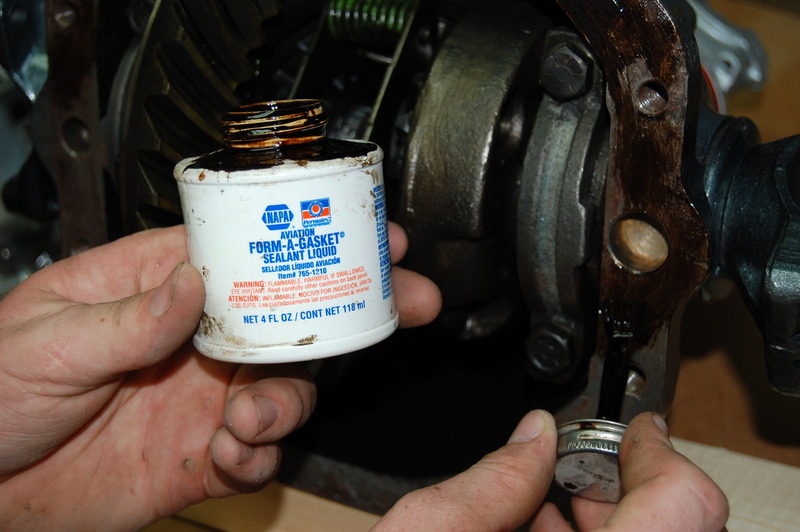
Part number 582213 differential assembly receives a coat of Permatex aviation sealer on both the housing and cover surfaces to prevent leaks.
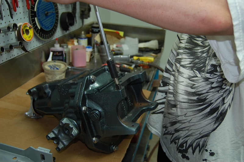
We installed our differential gasket and cover now the Totally Stainless 7/16-14 bolts are torqued to 65 lbs/ft.
To make sure our rear spring bolts tighten properly, a 9/16-18 tap is used to clean the threads. We also use a 3/8-16 tap on the differential housing side next to the spring mount pad. It is also a good idea to clean the 7/16-14 threads with a tap for the differential cross member on the opposite side.
Our camber strut bracket is installed, torquing the 3/18-16 bolts to 45 lbs/ft. The camber strut bracket bolts must not protrude more than ¾” past the bracket. Longer bolts can pierce the differential housing. The front differential mount bracket is installed next. These 7 1/6-14 bolts are torqued to 65 lbs/ft.
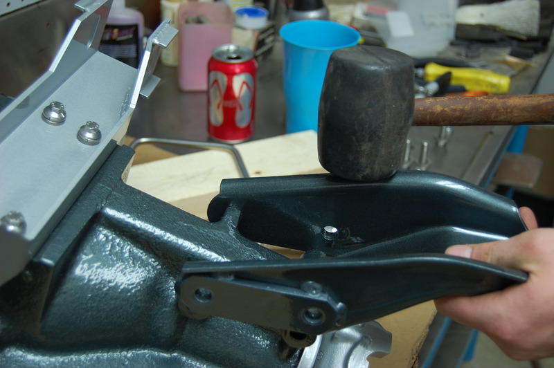
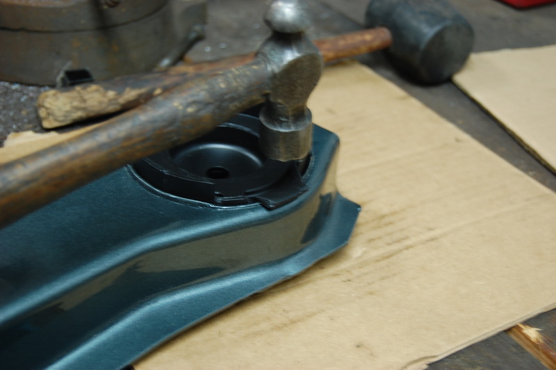
Before we install the differential cross member onto the differential housing, we are installing the outer cushions, part number 582005. The cushions press easily into the cross member with light force. A hammer is used to fold the edges of the cushion over.
Photo of prepping front hubs
We prefer to replace the forty-plus-year-old wheel studs. Here we are using a homemade fixture that holds the wheel hub level for stud installation.
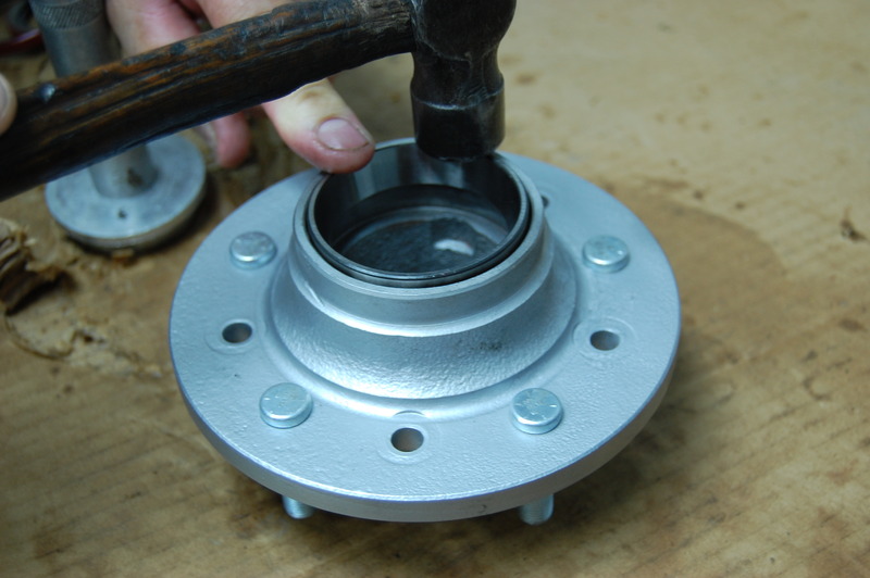
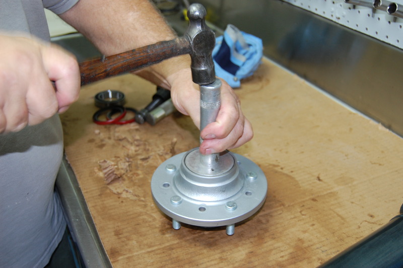
Like the rear wheel bearings, the front hub races must be installed. We are using a small ball peen hammer to start the races, making sure they are going in straight.
The bearing race installation is finished off with a swap meet purchased installer. This bearing race installer kit was found at Corvettes at Carlisle for a very reasonable price.
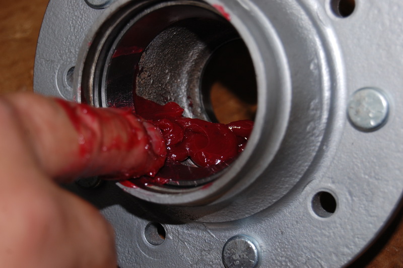
We pack the front wheel bearings in the same manner as the rear. We are showing the placement of some additional grease in the hub. The idea is bearing longevity if the bearing were to lose grease from high heat.
Chassis Assembly
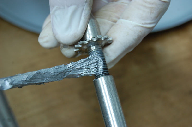
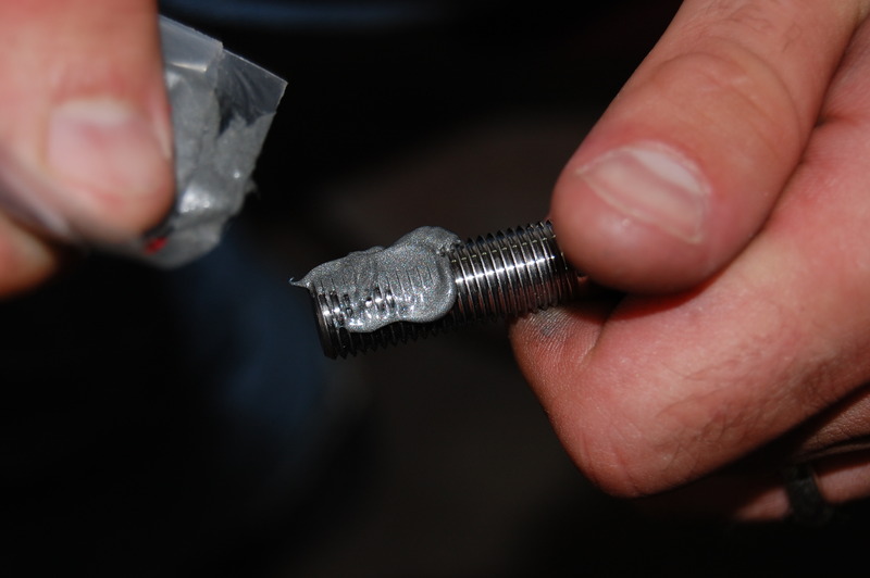
Our chassis assembly started with Totally Stainless fasteners, one of the many new products Corvette Central has available. Chassis fasteners have been a long-term concern. Eventually, original equipment fasteners discolor or corrode due to climatic conditions. These stainless steel fasteners are high-grade hardened steel to provide security. The stainless products are complete suspension kits to replace the majority of OEM fasteners. All of our hard work painting will be complemented with high-grade fasteners. Our fasteners will be looking good for years to come. One very important concern with stainless steel fasteners is galling of the threads. Galling occurs as the stainless steel smears onto the other threads. Heat also builds up as the bolts are threaded into each other. The best solution is to apply an anti-seize compound to the bolt threads before installation as a lubricant. This is one step that you must remember if you decide on using any stainless steel fastener.
Fastener torque is something we try to watch carefully. If at all possible, we torque each fastener using the factory specs. Trying to “feel” how tight the fasteners are can get you into trouble. Taking a few extra minutes to torque fasteners can save a lot of grief later. Torque specs are available in all GM service manuals. Always use the manufacturers’ fastener torque recommendations when using aftermarket pieces.
Photo of anti-seize use
Here we are applying a coating of anti-seize to the Totally Stainless chassis bolts.
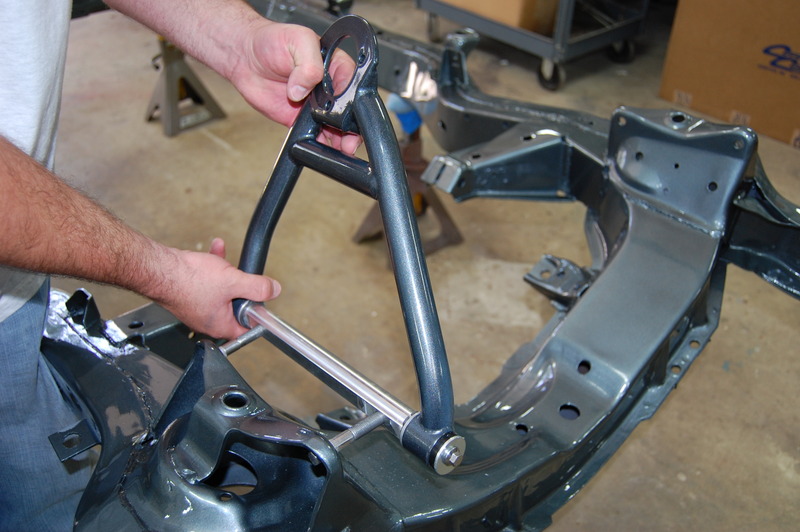
Now we really are ready for assembly of all the components onto the chassis. Be aware of where the jack stands are placed to avoid an unbalanced condition. Place them close to both ends of the frame. Chances are the front or rear could be lifted up if the stands are closer to the center of the frame. We’ll cover the front suspension installation first. Our upper and lower control arms are Van Steel tubular pieces with urethane bushings that will enhance our suspension geometry. The upper control arms install like the originals with shims to adjust the caster, camber, and toe. Lower control arms are installed with Van Steel supplied hardware due to the control arm pivot shaft design.
Front Suspension
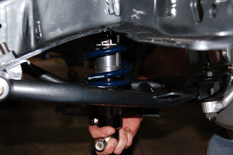
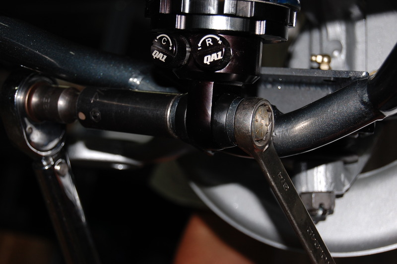
Van Steel coil-over front springs with QA1 shocks are installed to replace the antiquated original equipment coil springs and shocks. The QA1 shocks are double adjustable for precision suspension tuning. We can adjust compression and rebound for just about any road condition. Vehicle height can also be adjusted by simply turning the spring load nut. One very nice installation aspect is the coil-overs install much easier than traditional coil springs. The spring load nut is backed off fully before the coilover/spring assembly is installed. Our front suspension assembly is wrapped up once the spindle and steering arms are installed.
Photos of front suspension installation
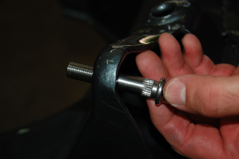
This Totally Stainless upper control arm retaining bolt has serrations to hold it in the frame. Another nice feature is the bolt head is taller than the original—these bolts, even when serrated, tend to come loose over time and spin during front-end alignment. The tall nuts allow you to use a wrench to hold them if necessary.
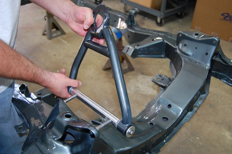
Van Steel upper control arms are being installed with the long tube of the control arm forward. We are using the complete Corvette Central kit number 572389 with all the necessary pieces in one package.
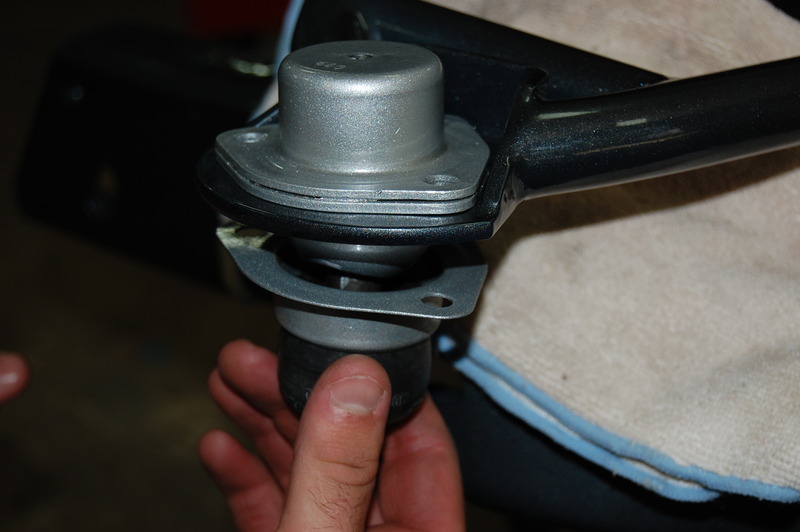
New upper ball joints are installed in the upper control arms. Note that this set of ball joints has a steel retainer for the grease boot. Make sure you read the instructions on how they want the boot and retainer if equipped installed.
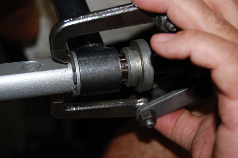
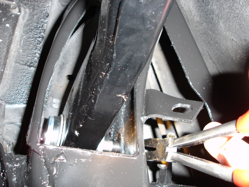
The lower control arms have snap rings to hold the bushings in place like the uppers. We are using a gear puller to position the snap ring properly.
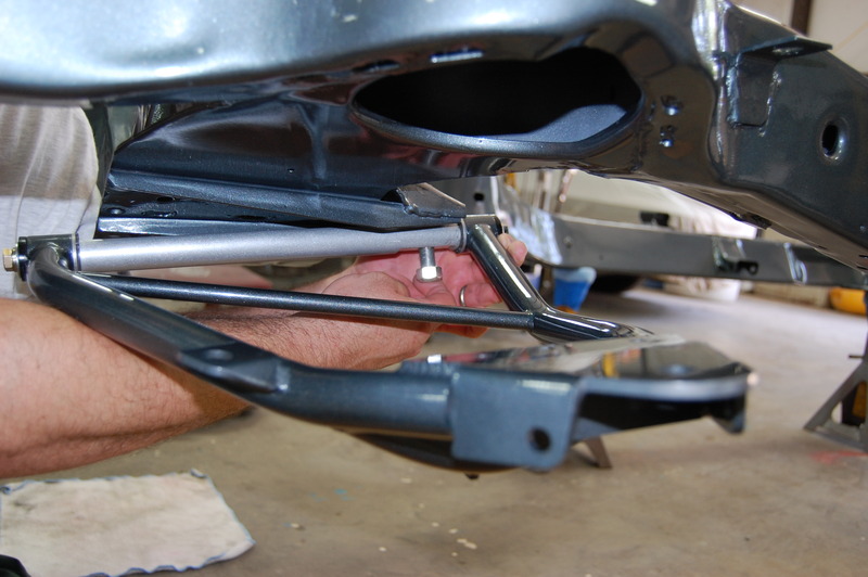
We used Van Steel’s rear bolt, which has a smaller diameter than the OEM bolt. Van Steel provides a sleeve to take up the slack from the bolt diameter difference. Make sure you check out the assembly instructions.
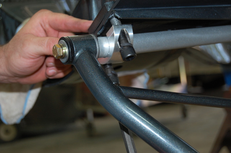
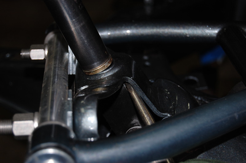
A different configuration is used on the front lower control arm shaft to retain it. The original nut plate is used to reinforce the frame area with the new aluminum retainer bracket and bolts.
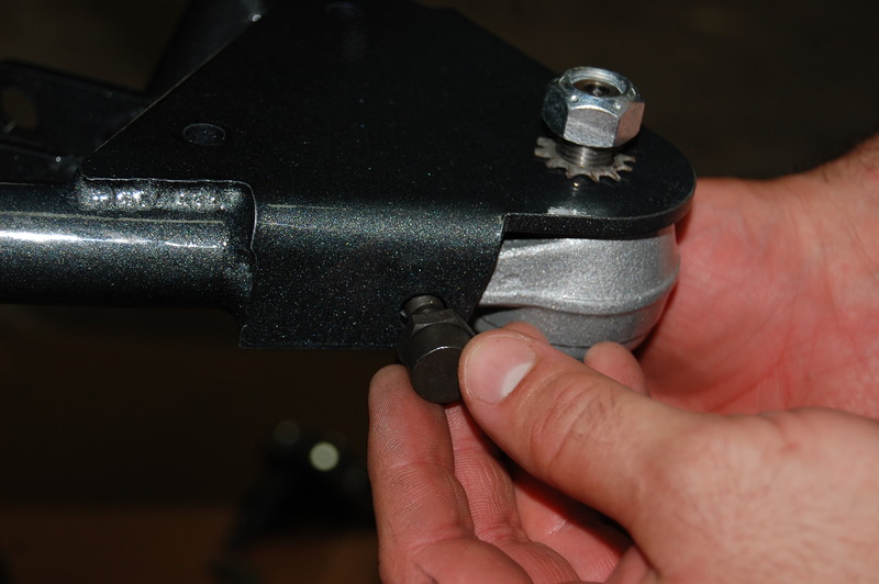
OEM style lower ball joints are used in the Van Steel tubular lower control arms. All of the OEM installation hardware is included with the ball joint kit and works with the new arms.
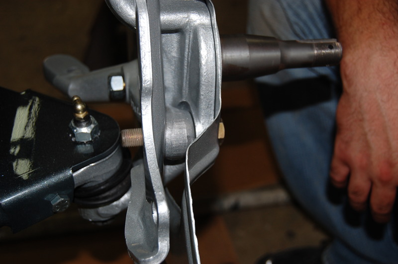
The spindle, steering arm, caliper mount, and brake backing plate are installed next. We used new grade eight hardware to install the steering arm and caliper mount plate. The upper ball joint stud is torqued to 50 lbs/ft. The lower ball joint stud is torqued to 80 lbs/ft. The prescribed torque reading is obtained on the upper and lower ball joint studs. The castellated nuts are tightened until the next slot is open for the cotter pin.
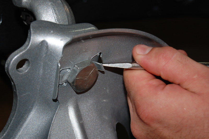
The upper brake backing plate/caliper mount bolt requires 90 lbs/ft of torque. Be careful during torquing, as the short bolt head can be easily slipped off. Make sure you bend the tabs over that keep the bolt from moving.
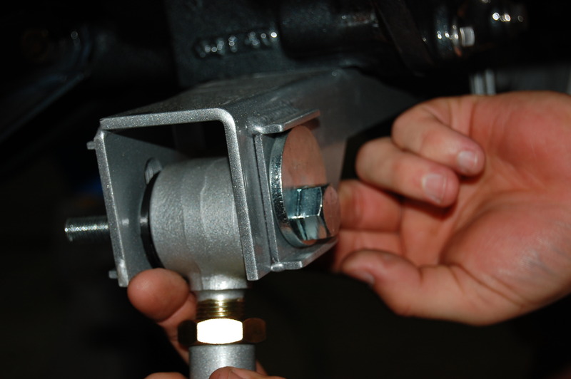
Now we install our Van Steel coilover spring/shock assembly, which is part of the number 572389 kit. We took a minute to sand off the upper through bolt that retains the shock to the adapter bracket. We cooled the nut with a wet cloth to prevent damage to the nylock lock-nut as we were modifying it.
We backed the spring load nut off completely and installed the assembly. With the spring unloaded, we could easily install the coilover assembly. Before lowering the chassis, we will raise the load nut at least five or six turns.
Once the lower coilover assembly bolt was installed, we torqued it to 90 lbs/ft.
The upper coilover nut was torqued to 65 lbs/ft with a screwdriver holding the adapter assembly straight.
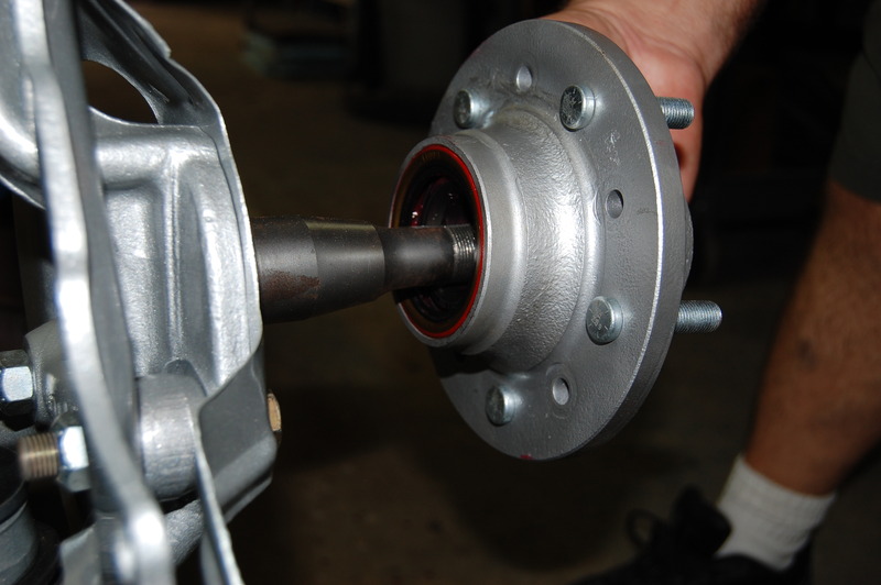
Now our previously prepped wheel hubs can be installed. Be sure to wipe some of the wheel bearing grease onto the seal. This prevents burning the seal material during the first few rotations of the wheel.
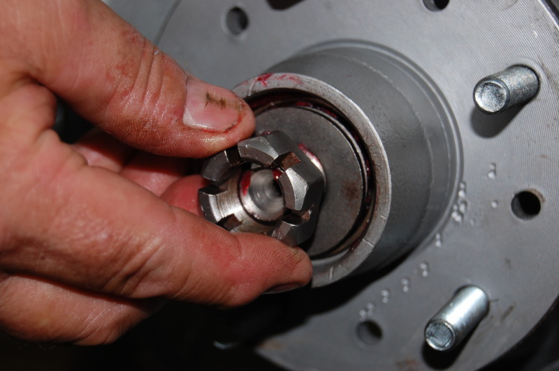
After packing the outer bearing with Mobil 1 synthetic chassis lube, the washer and nut are installed.
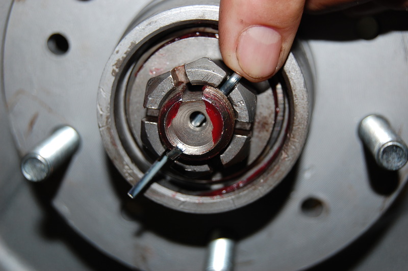
Adjusting the wheel bearings is next. We run the nut down tight to seat the bearings while rotating the hub. The idea is to have zero end-play in the hub assembly without causing drag. It takes some time to get a feel for it. If the nut is loose and the next slot requires 1/8 of a turn to line up the cotter pin hole, go for it. If it takes a full slot tightening to line up the hole, back it off to the closest slot and install the cotter pin.
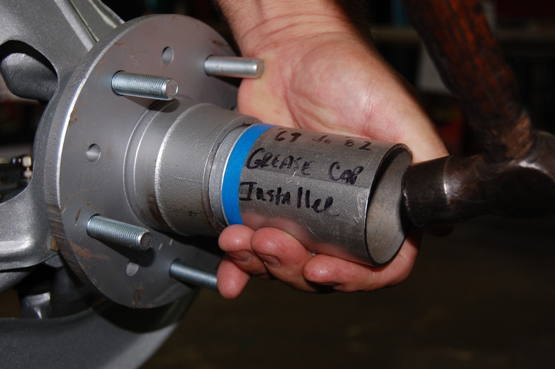
This may seem insignificant, but it really bugs us to see the dust caps full of plier and hammer dents. We always use a chisel to remove the cap, gently tapping it at the lip until it is off. This is a piece of thick-wall exhaust pipe that we made into our installer.
Steering
Our dilemma: do we use traditional GM power steering assist or go with something better? The original GM components worked well, although they were prone to leakage. The power steering control valve has multiple hoses as possible leak points. The use of the steering assist cylinder, which can be easily damaged, is the other issue. All the sensitive power steering components, including the steering assist cylinder, are subjected to road grime.
One well-thought-out steering gear product is the Borgeson replacement steering gear. Borgeson has a replacement power steering gearbox that eliminates the need for the control valve and cylinder on the steering linkage. The new gearbox bolts directly in place of the original box. Steering linkage changes are required to couple the new box. Two options are available: an adapter that uses the original power steering linkage or a manual steering linkage center link. The least costly alternative is the Borgeson adapter. Using a manual steering center link will also require replacing the pitman arm. The manual steering center link pitman arm is configured differently, causing problems if you try to mix them. Borgeson also has hoses available to connect the new box to the existing power steering pump.
We went with the Borgeson box, and new tie rod ends for our steering linkage. Corvette Central had a good used manual steering pitman arm and center link to finish the installation. The only piece we would need on the passenger side of the steering linkage would be a new heavy-duty idler arm.
Photos of steering installation
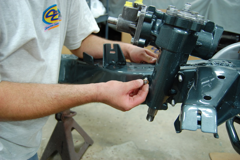
Here we are installing part number 563067 Borgeson steering box on the chassis. We used the OEM 3/8-16 carriage bolts for the frame with stover nuts and washers. It sure looks like it belongs on our freshly painted frame. Torque these nuts to 30 lbs/ft.
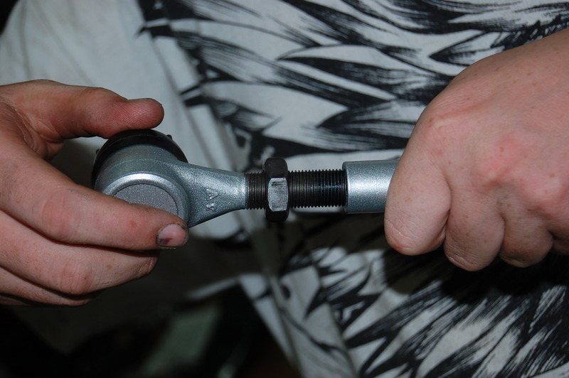
New tie-rod ends are screwed into part number 572236 heavy-duty sleeves to complete our steering linkage.
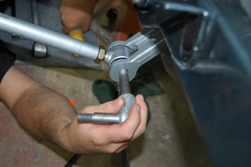
We are loading the pitman shaft ball stud assembly into the manual steering center link. CC has a convenient kit (part number 562017) with all the pieces in one box.
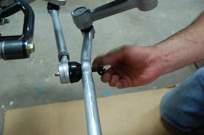
The tie rods are installed on the center link using torque. Turn to the next available open slot procedure. First, we torqued the nuts to 36 lbs/ft, and then we turned them to the next available slot.
Rear Suspension
Next, we’ll install the rear suspension, starting with the differential. Although the differential is technically a driveline component in this application, it is also the rear suspension pivot point. GM designed a very simple independent rear suspension with the trailing arm being held at the bottom with the strut rod. Vehicle weight keeps the axle shaft tight against the differential assembly. The design does have limitations with major changes in the rear suspension camber. As the rear wheel goes through its full up and down movement, the camber goes from positive to negative. Corvettes are not typically used off-road, so this suspension design works well.
We install the differential as an assembly with a cross member and front differential mount. Once the differential is in place, trailing arms are installed. Something to remember is the trailing arm bolts are installed from the inside with the nut on the outside of the frame rail. If the bolts are installed in the other direction, they would require cutting for removal once the body is in place. We usually put equal shims on both sides of the trailing arm bushings for an initial alignment.
Photos installing differential
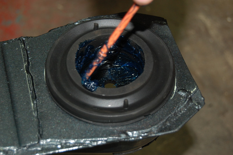
We always apply some grease to the frame to differential cushion coupling cups. This will be beneficial if you ever decide to remove the differential later.
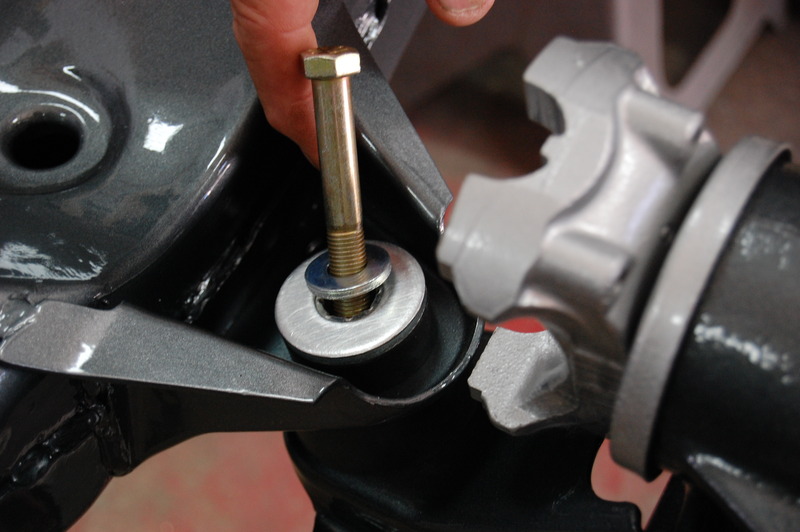
The differential is raised into place on the frame centering the cushions on the cups. The 7/16-14 bolts are torqued to 65 lbs/ft after both bolts are started and snugged down.
We installed the front differential mount cushion next. There are two trains of thought here: use urethane which would transmit drivetrain vibration into the frame, or use rubber. The rubber cushion flexes but keeps the vibration and noise down. We opted for the part number 582002 rubber cushion kit for a smooth, quiet ride.
With the differential in place, we can finish installing part number 582237 Smart Strut rear strut assembly. The Smart Strut assembly lowers the strut rods as much as possible, stabilizing the rear suspension geometry.
Photo installing trailing arm
We used this photo to make sure it’s understood that placing the bolt in from the correct side is important. It also shows how much easier it is to install the trailing arm pivot bolt with the body off.
If we assemble the trailing arm spindle housing on the correct side, the shock mounts will install next. NEVER use your fingers to line up any suspension component. Please use a line-up bar. These shock mounts go in easier if the trailing arm is picked up level with the frame.
Trailing arm shim note:
GM used slotted trailing arm shims starting in 1971. They saved a lot of grief for the alignment man. Early Corvettes can use the slotted shims with this suggested modification. When the slotted trailing arm shims were introduced, GM modified the frame. A 3/16” hole was drilled so that a long cotter pin could be installed to prevent the shims from moving. We found that drilling the frame was a requirement to prevent shim loss. Every time we change the shims to the later style, we drill the frame. The trailing arm shims adjust rear toe-in or toe-out. When the trailing arm shims fall out, the rear toe changes dramatically, causing rear steer, especially on and off the throttle.
Rear-axle installation is our next endeavor. Once finished, we will have a complete rear suspension.
Photos assembling axles
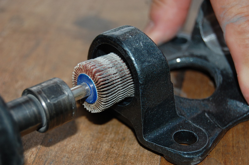
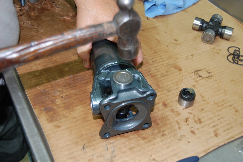
This is our secret to the easy installation of u-joints. We use a fine grit flap-style sanding wheel to remove corrosion and paint from the u-joint cup surfaces. Exercise care, as too much cleaning can make the cups fit sloppily. Clean them just enough to be shiny. Stop as soon as the paint and corrosion are removed.
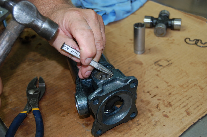
Many assemblers use presses and vises to install the u-joints. We prefer to install the u-joint trunnion holding it above where it would typically position itself when assembled. This allows us to set the cup into the trunnion, preventing the cups bearing needles from falling out. The cup is gently tapped into the axle shaft even with the yoke end.
The shaft is rolled over, and the same technique is used to install the other cup. Once you get the hang of this installation procedure, you can feel if any problems arise as the cups go into the yoke.
ALWAYS make sure the retaining rings are seated into the yoke. Also, check to make sure the yoke rotates easily without any binding or crunching sounds. Cleaning the u-joint surfaces is the key to easy assembly without losing the needle bearings during assembly.
Photos installing axle
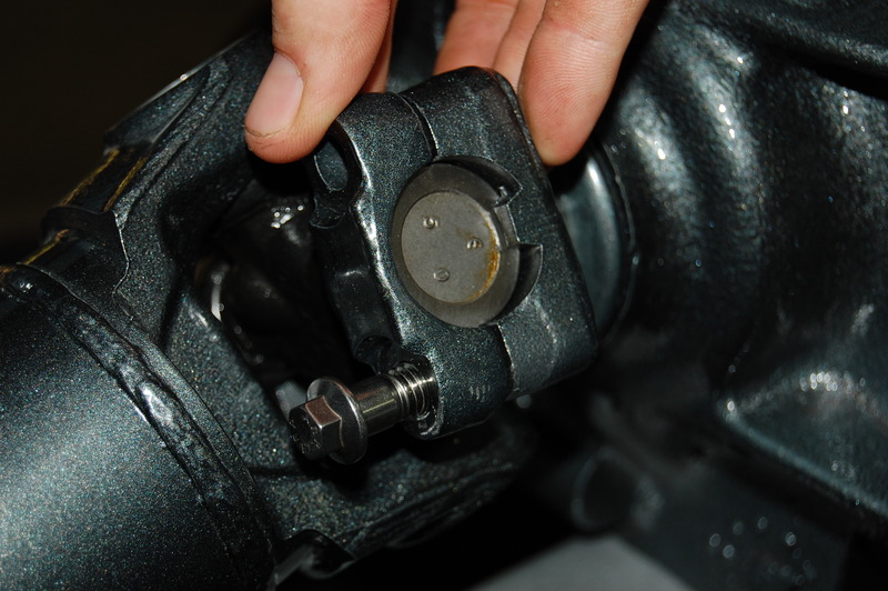
We are using heavy-duty u-joint straps for this project. Our Totally Stainless bolts are being installed. We torqued these 5/16-24 bolts to 30 lbs/ft.
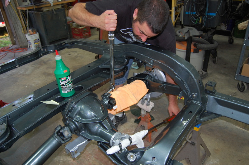
Austin is using a large pry-bar to hold the pinion as he torques the axle shaft bolts. The outer 7/16-20 axle shaft bolts are torqued to 65 lbs/ft.
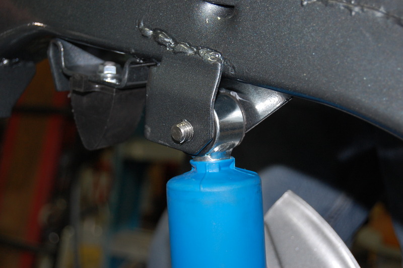
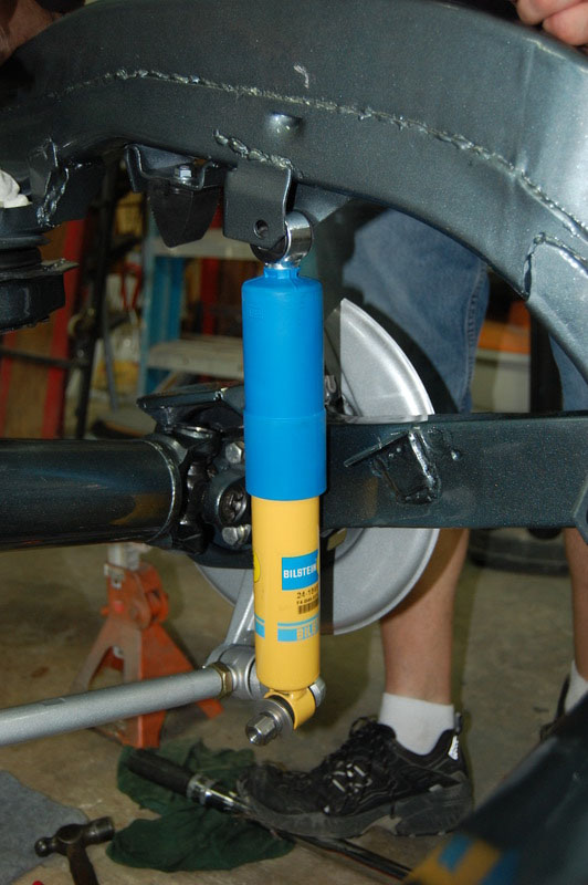
We find it easier to install our part number 582212 Bilstein shocks at the upper location first. The shock bolt goes in from the outside of the frame rail. Installing the bolt from the inside will make it impossible to remove once the body is in place. We torque this nut and bolt to 50 lbs/ft.
The lower portion of the shock installs easier if the trailing arm is lifted up somewhat. This 1/2-20 lower shock mounting nut is torqued to 60 lbs/ft.
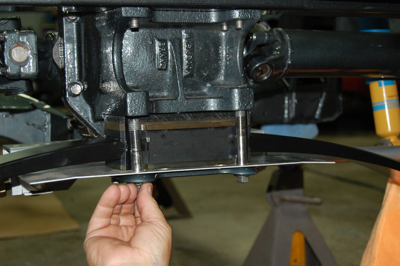
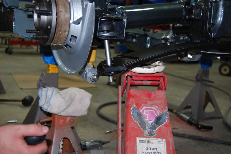
Our part number 582410 rear fiberglass mono spring is installed next. We choose the 300 lbs spring for good overall ride quality. Stiff shocks and high spring rates can make the rear lose traction on rough roads. The tires do not stay planted to the pavement; they hop over it.
The rubber rear spring cushions are installed using the jack to load the spring. Notice that we have the jack-plate sitting on the metal portion of the spring. This is very important, as gouging the spring can cause catastrophic spring failure.
Our next phase of this ground-up restoration will finish all the necessary items for the rolling chassis. We will show our brake system installation with all related lines. Our electronic fuel-injected engine will require a fuel tank upgrade and lines.
Story and photos courtesy Chris Petris






Hello. I have c2 1963. 63-82 LOWER TUBULAR FRONT A-ARMS / CONTROL ARM – PAIR (USE WITH STOCK SPRING AN) 572272. This will help remove the positive camber. Thanks