Please read the entire instruction sheet before attempting assembly, as we will not accept returns or warrant bars scratched by improper assembly techniques.
First, unwrap all parts and inspect them.
Check to make sure you have all the parts listed.
If you run into a problem please call product assistance (800-345-4122).
Parts list:
1 center bar.
1953-57 bars have 13 holes and are 37 ¾” long.
1958-60 bars have 9 holes and are 27 ½” long.
9 or 13 Teeth:
1953-57 has 13 teeth
- 1 “C”
- 6 #1
- 2 #4
- 2 #5
- 2 # 6
1958-60 has 9 teeth
- 1 “C”
- 2 #1
- 4 #4
- 2 #5
18 or 26 Studs:
26 studs for 1953-57
18 studs for 1958-60
18 or 26 Nuts:
26 nuts for 1953-57
18 nuts for 1958-60
18 or 26 Lock washers:
26 lock washers for 1953-57
18 lock washers for 1958-60
9 or 13 Plates:
13 plates for 1953-57
9 plates for 1958-60
Tools needed:
7″ or larger locking pliers.
7/16″ open end wrench
Masking tape
Loctite (optional)
Notes:
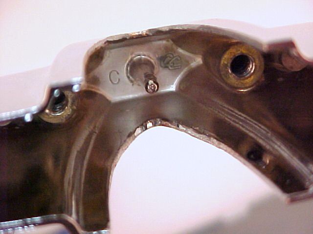
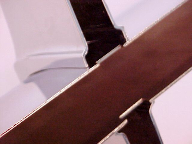
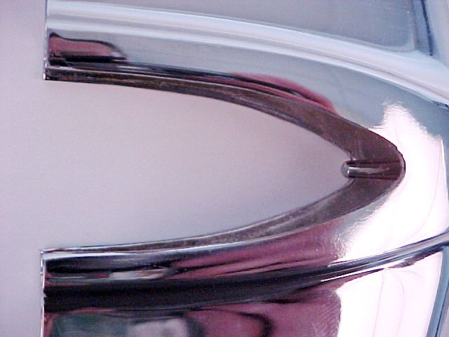
Every tooth has a number cast inside. The center tooth has a “C”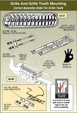
Teeth used are: C, 1, 4, 5, 6. Teeth 2 and 3 were not produced.
The bar is made so that the teeth will be tight when in place. To properly install the teeth, you will need to squeeze the bar slightly.
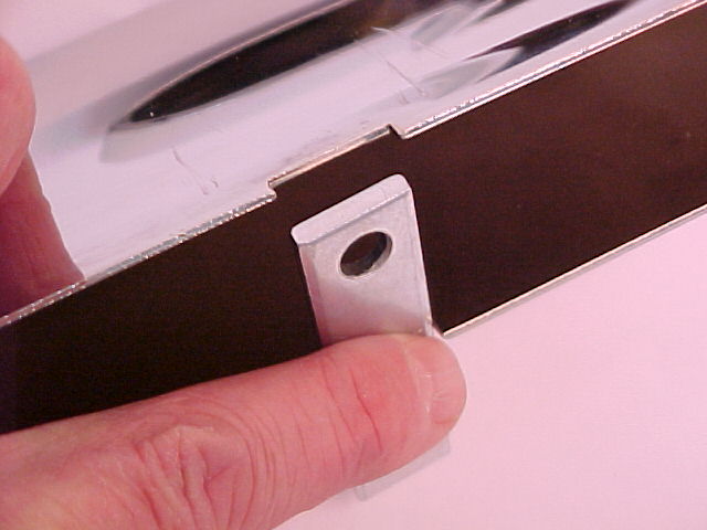
The back of the bar has notches for the alignment plates that slip onto the tooth studs.
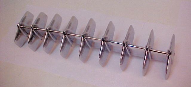
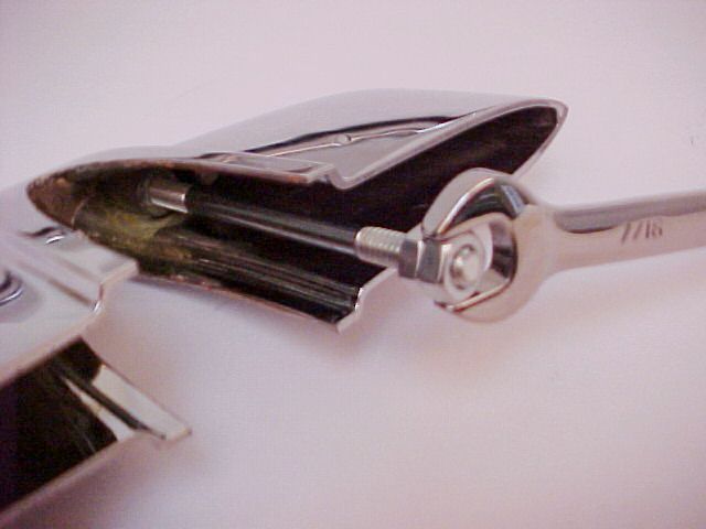
Install the studs into the teeth. You should be able to do this with your fingers. Use Loctite if you choose. “Double nut” and finish tightening them.
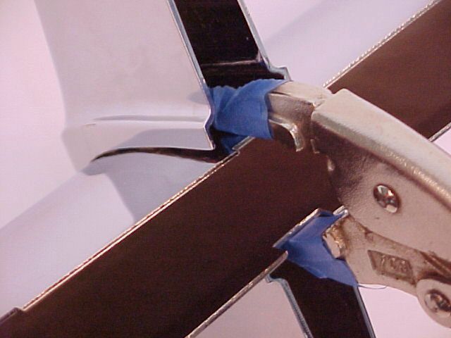
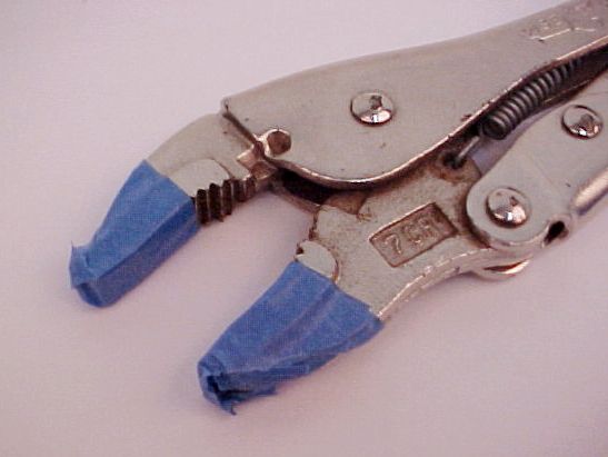
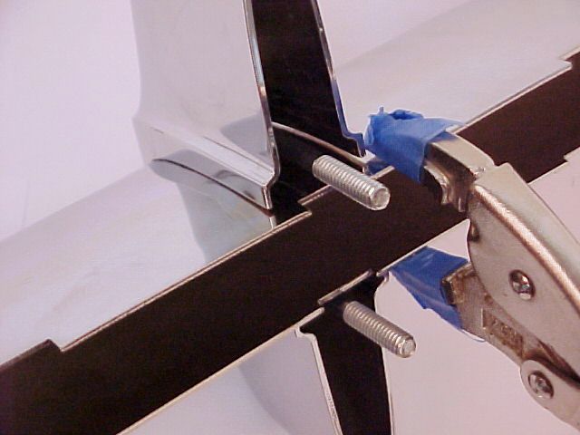
Wrap the jaws of the pliers with several layers of masking tape to protect the chrome on the bar. It wouldn’t hurt to put tape on the bar as well.
Adjust the jaws of the pliers so that when they are locked, the edges of the bar will be squeezed together about 1/8 inch.
Begin in the center. Find the “C” tooth. For this tooth it does not matter which way is up.
Squeeze the bar about ¼” to the side of the center notch and slide the tooth into place.
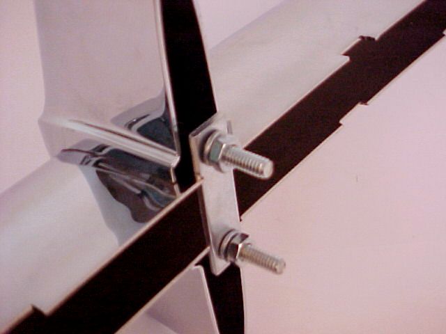
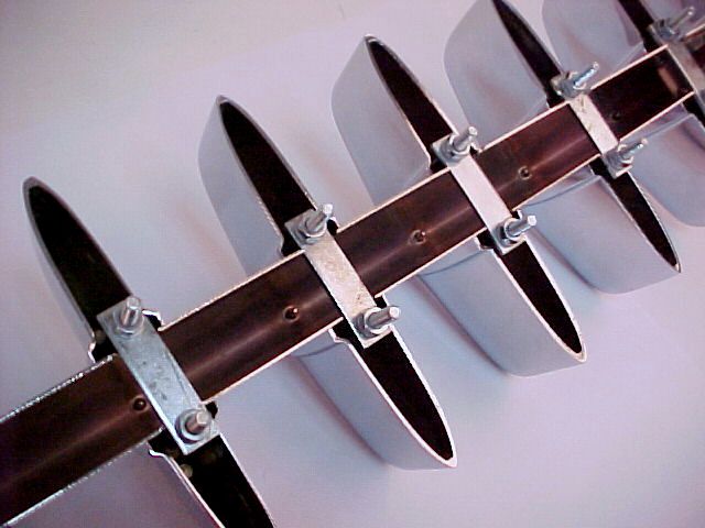
Drop a plate onto the studs followed by lock washers and nuts.
Finger tighten before releasing the pliers. Use the wrench to finish tightening.
The next teeth are the #1 teeth. It matters which way is up on all the remaining teeth. Look at the arch-shaped opening on each side of the tooth. Notice that one side extends farther forward. The reason is because the bar is curved and the teeth need to face straight forward.
If you look closely, you will also notice that the outer teeth are a bit shorter.
Clamp the bar again and install the #1 tooth. It should slip straight on. If it doesn’t, flip it over and try again.
Continue installing teeth with the numbers increasing as you move to the end of the bar, until all the teeth are installed.
Story and photos courtesy Gus Gustafson, Corvette Central Product Assistance

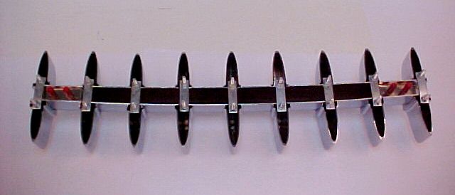
Could you tell me which is top of the grille mounting brackets (421011)
Thank you Jack Schroeder
The notched ends go towards the top of the grille, and the longer brackets go in the center.
Is the GM part number casted on the inside of the teeth. with the reproduction ones, like the original were for GM? Thank You Fred
The inside of the teeth have the number – “C”, or, 1, 4, 5, 6, and the Corvette Central “CC” logo.
You can see this in the first photo in the instructions.
Regards,
Gus
Corvette Central Product Assistance
Can you please provide a picture of the proper mounting of the mounting bars to the teeth assembly once both the backing plates and mount bars are installed? Is the order:
1) tooth > stud > backing plate > lock washer > nut > mount bar > lock washer > nut
2) tooth > stud > backing plate > mount bar > lock washer > nut
If #2, the lock washer get wedged into the mount bar and does not seem to be effective as a lock washer. Maybe a better way to phrase the question is how does the mounting bar get secured?
The lock washer is on the back side of the mount bar, but because of the way the mount bar is curved, I could see how maybe it wouldn’t seat. Filing/grinding some material off the outside of the washer or the inside of the mounting bracket to make enough clearance to help the lock washer seat flat may help, but this isn’t something we hear people normally needing to do. If you want to send us an email to mail@corvettecentral.com . We can send you some additional installed photos showing the lock washers in place.
I still can’t determine the top and bottom of each tooth so that I can mount them in proper order. Is there any consistency with the markings inside each tooth. Is the “CC” always stamped on the top? If not, could you supply a better diagram of determining the top or bottom?
The location stamp is directly under the stud (bottom). C for center, 1 for 1, etc. This will tell you the locations. Page 85 in our C1 catalog shows the order in which each tooth is placed. The grille assemblies on our website show these views as well.
421020, “C” = 7 1/4 inches tall
421021, “1” = 7 1/4 inches tall
421022, “4” = 7 1/8 inches tall
421023, “5” = 7 inches tall
421024, “6” = 6 5/16 inches tall