Does your 1963-1982 Corvette keep you on your toes when cruising on the highway? Are you constantly moving the steering wheel back and forth to maintain a straight line? Maybe you need to move the steering wheel a couple of inches in each direction before the steering linkage catches up. The culprit may be t
he steering coupler and steering box.
The steering coupler is a rubber disc reinforced with cord to isolate the normal road vibrations that occur. The rubber disc part of the coupler looks like a piece of tire material. Over time, it deteriorates. There is a safety device that uses two pins captured by the upper and lower halves of the coupler. This safety device prevents a total disconnect between the steering shaft and steering box. At the coupler, the play from a torn rubber coupling may appear minimal. The steering wheels larger diameter exaggerates the minimal play as well. Finding out if this is the problem requires someone rotating the steering wheel back and forth while you look at the steering coupler. If you see the safety pins hit the coupler housing while the steering wheel is rotated, the coupler is shot. Another sign is deformed rubber from oil or brake fluid dripping on the coupler. It surprises us how many people miss this minor problem that causes a big concern.
If the coupler is good, the extra steering wheel movement may be due to steering gear box wear. 1963-1982 steering gear boxes are all manual with a power steering assist cylinder if so equipped. Manual steering boxes are bulletproof. However, they are prone to getting looser, causing more play in the steering wheel as they age. Many of the manual steering gear boxes have never been overhauled or checked for lubricant. GM used wax-based chassis grease in the early units. As years go by, the lubricant that was suspended in the wax base settles to the bottom. When you take a steering gear apart, the lubricant is one coagulated mess with very little lubricating capacity. If the steering gear has not been overhauled, now is the time to do it. After overhaul, we use 80-90W synthetic differential gear oil to keep the box moving smoothly for many years. Of course, you can adjust the box and leave the nasty old grease in place. The longer you wait, the more costly the overhaul will be.
Adjusting the gear box is easy enough if you follow a few simple rules. The steering gear must be centered for correct end play adjusting. It is always better to have the gear adjustment just a bit loose rather than too tight. The steering gear consists of the pitman shaft and worm gear sector. All steering boxes have a high crown center gear tooth pitman shaft with slightly smaller outer teeth. You want the steering gear box to feel tight with no play when you are cruising down the highway. The high crown tooth on the sector gear maintains a tight feel. As the steering gear is turned away from center, the smaller teeth prevent any binding that might occur. The benefit is the smaller teeth also allow the steering wheel to return to center more easily. If the steering gear is adjusted when the steering gear is off center, the smaller teeth will require a major change to tighten the steering gear. The problem arises when the steering gear passes the center position, causing a bind to occur. Making sure that the steering wheel is centered is only part of the solution. We see from time to time where accident damage
was repaired and the steering gear was not centered because of frame damage. In this scenario, the tie-rods get adjusted to make up for the off center gear box. If the steering box is binding, check the present position of the pitman shaft. Start by turning the steering wheel from lock to lock counting the turns required. Once you have our number of total turns required, divide the number of turns required in half. This divided number would give you the number of turns to locate our centered position. Turn the steering wheel completely to the right or left and go back to the center position the number of turns you previously divided. Once the gear is centered, you can go ahead with our adjustment.
If you found out that the steering gear was not centered (indicated by an unequal number of left or right turns required) after the wheels are pointed straight ahead, the most logical explanation would be a bent steering linkage component.
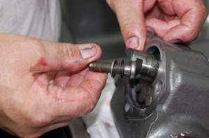
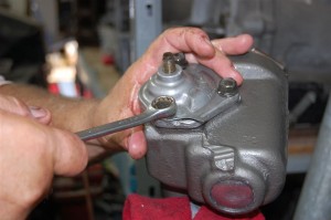
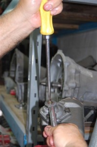
The adjustment of the steering gear is simple: a 5/8″ wrench is used to loosen the lock-nut and a flat bladed screwdriver is used to make the adjustment. Turn the adjusting screw down clockwise until resistance is felt, then back off the screw a quarter turn. While holding the adjusting screw with the screwdriver, the 5/8″ wrench secures the lock-nut.
With the steering gear freshened up along with a tight coupler and proper alignment specs, your 1963-1982 Corvette will feel like a new car.
Tool/Equipment Requirements
Small screwdriver
Large screwdriver
Flat bladed chisel
¼” round point chisel
Modified flat chisel (bushing cutter)
3/8″socket set
1-3/8″ inch socket or wrench (pitman arm nut)
Large pair of Channel-Lock pliers (for worm shaft adjuster cap)
Bushing/bearing installer kit (Corvette swap meet vendors have reasonable cost kits)
Pitman arm remover (rent from local auto parts store)
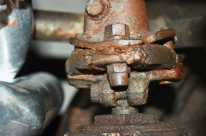
Forty-two years of brake fluid, engine oil and exhaust heat have taken a toll on this steering coupler.
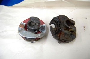
Corvette Central has an original replacement #563135 steering coupler for 1969-1982 Corvettes along with other suitable low cost alternatives.
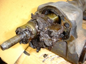
This 1979 Corvettes steering gear lubricant is nasty. Not much lubrication going on here; waxy gunk is stuck to everything. Exhaust heat has been cooking the lube oils out for many years.
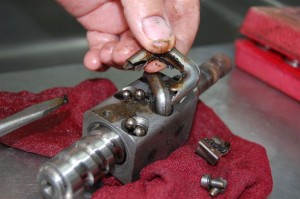
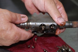
This step is usually not taken when the steering gear is serviced. The recirculating balls wear down from poor lubrication.
Dump the balls out while rotating the worm shaft. These balls will be replaced. The worm shaft is very tough. However, it should be checked for pitting. If pitting is found, the worm shaft should be replaced to avoid a rough feel while steering.
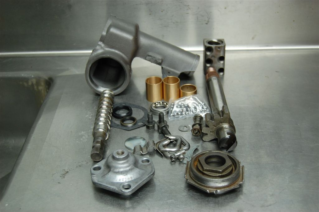
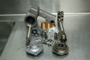
This is an exploded view of all the steering gear pieces for the 1963-1982 Corvette. Also pictured is a Corvette Central supplied Overhaul Kit #562137. There are a few differences from early to late. The major difference is the top cover at the lower left corner of the photo. This 1977 Corvette uses an aluminum cover. Some 1969 Corvettes and all earlier models have a cast iron cover. 1963-1968 Corvettes have a round splined input worm shaft. Some early 1969 Corvettes also used the round input shaft. In theory, all round input shaft steering gear boxes should also have a cast iron pitman shaft adjuster cover. During the 1969 build year, the input worm shaft was redesigned with a flat side to prevent steering coupler spline slippage. When the worm shaft was redesigned, the cast iron pitman shaft adjuster cover was replaced with an aluminum assembly. There is no definite production point or VIN that denotes when the later style input worm shaft and adjuster cover was implemented. Since 1969 Corvettes can have either style input shaft, you should see what you have before ordering your new coupler. While it is possible to install the round style input shaft coupler on a later flat style input shaft, it is not recommended. Corvette Central has flat or round style input shafts. Telescope columns are also available.
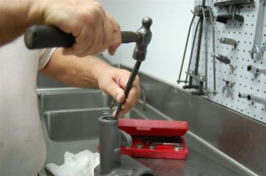
Our small hammer and punch is used to loosen the pitman seal from the bore. Be careful here. Gouging or nicking the seal bore can cause an unexplained leak.
You may have noticed the steering gear box looks clean and has the correct color. We cleaned the housing and then coated it with Corvette Centrals #101020 cast iron coat. Once the seal is loose, a large screwdriver can be used to remove the seal.
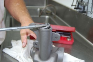
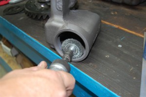
Why clean and paint before removing the bushings and seals? To avoid damaging the seal and bushing surfaces during the cleaning process. A wire wheel is used to clean the worm shaft/sector gear adjuster cap threads.
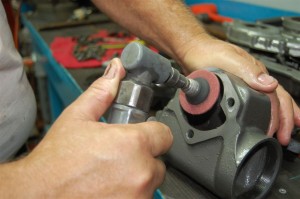
This is the only paint we need to remove from our painting process. The maroon medium grit scotch-brite wheel provides a clean and shiny gasket surface.
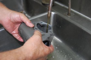
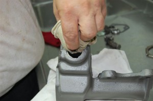
A thorough washing is next to remove any grit from the scotch-brite disc. The gear box housing should be blown dry with compressed air to avoid lint from shop towels sticking to the cast surfaces.
The inner worm shaft bearing race is removed using a drift punch. Tap it side to side to avoid bearing bore damage.
Here we have used our bushing/bearing installer to install the inner bearing race removed previously.
Turn the gear box over and make sure the bearing race is installed correctly. This is an important step. Make sure the bearing race is seated flat in the bearing race bore.
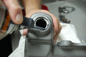
We wipe the worm shaft seal plug surface with Naphtha or brake cleaner to remove any residual oil or grease.
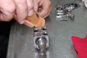
A bead of silicone is applied to the bore plug surface to prevent fluid leaks. Now that we are using 80-90W gear oil, it is important that this plug is sealed properly.
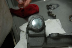
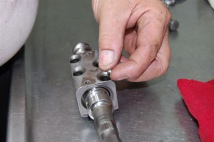
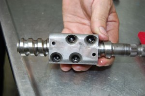
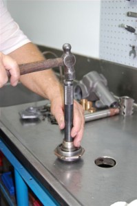
The bore plug from the Corvette Central overhaul kit is installed, tapping the center of the plug with a ball peen hammer to tighten it. The plug will expand as it flattens out slightly. You don’t have to be too aggressive with the hammer.
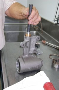
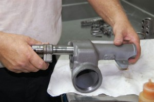
Now we are installing the pitman shaft bushings with our bearing/bushing driver tool. The same tool was used to remove the bushings. You need to be careful and keep the tool and bushing straight as it goes in.
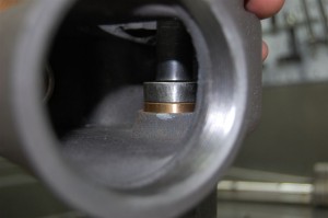
We need to tap the upper pitman shaft support bushing in just a little further, making sure it is flush with the housing surface. The lower bushing should be flush with the seal surface bottom bore.
If we installed the bushing carefully, the pitman shaft should slide easily into the gear box.
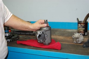
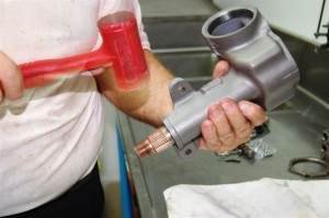
The pitman shaft should rotate freely in the gear box bushings. If there are any tight spots, a few taps with our plastic covered hammer loosens things up. This is standard bushing seating practice and will not harm anything. Turn the gear box and tap the shaft in at least four places to seat the bushings.
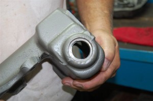
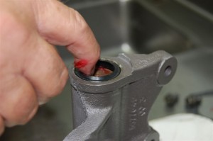
We cleaned the seal bore with Naphtha. Next we are apply Permatex Aviation Sealer to the bore to prevent leakage.
Our 1-1/8” impact socket is used to install the seal squarely in the seal bore. The important thing is to make sure the socket fits the outer circumference of the seal during installation.
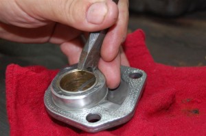
Now that the gear box is ready for assembly, we move onto the pitman shaft adjuster cover. Our especially ground removal punch cuts the bushing out. The flat blade punch has a half moon ground into it to provide two cutting edges.
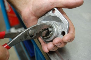
Once the bushing is cut almost completely through, pliers are used to grab the bushing and remove it. The cutting tool can do severe damage if care is not taken during removal. Keep the tool pointed away from the housing at all times.
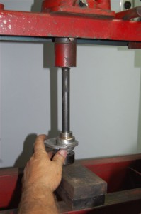
We prefer to use our press to install the pitman shaft cover bushing in order to keep it as straight as possible.
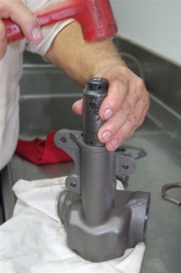
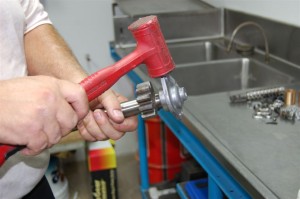
If you used a hammer to install the cover bushing, the same trick works on this bushing. Tap the housing with the plastic hammer in several locations to seat the bushing.
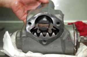
TIP: make sure you have the worm shaft installed correctly. There are alphas placed at each corner of the sector gear on one side. The alphas should face down with the splined portion of the worm shaft on the right. If the worm shaft is installed incorrectly, you will not be able to install the pitman shaft. We use the same 80-90W gear oil for assembly, lubing the bearings frequently.
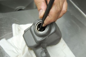
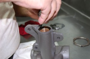
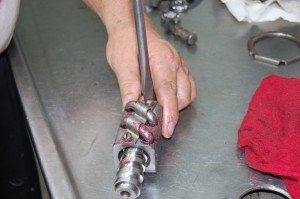
19 recirculating balls are installed into each track (one at a time), making sure they follow the worm shaft track. A small pick is used to push them around the worm shaft. Avoid rotating the worm shaft if possible. We rotate the worm shaft just enough to allow the balls to move freely during installation.
Both recirculating ball tracks are filled (even with the top) of the sector gear. At this point, DO NOT ALLOW THE WORM SHAFT TO ROTATE. Lock-up can occur during shaft rotation if any balls spill over into the other worm shaft tracks.
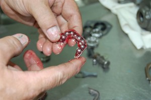
Eight recirculating balls are placed in the races with Trans-Jel lubricant. Trans-Jel is colored petroleum jelly that dissolves in lubricating oils when heated.
Both recirculating track races are installed first. The retainer is installed next.
Do not forget this very important step: rotate the worm shaft back and forth several times to assure smooth operation. If any balls inadvertently were misplaced, there will either be binding or one of the misplaced balls could fall out on the bench. If either occurs, you need to start over.
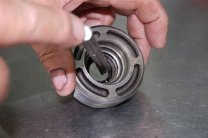
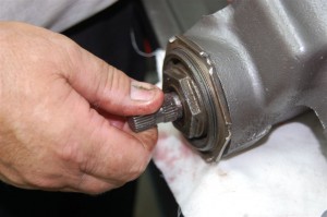
Now we can work on the worm shaft bearing pre-load adjuster cap. The seal is removed with a pin punch from behind.
Turn the adjuster cap over and tap the upper bearing race out with the pin punch.
Carefully tap the upper bearing race into the adjuster cap. C heck carefully to assure that the bearing race has seated fully.
We installed the seal with Permatex Aviation sealer after cleaning the seal bore surfaces with naphtha. A coating of Trans-Jel is applied to avoid burning the seal until lube reaches the seal.
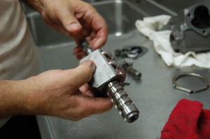
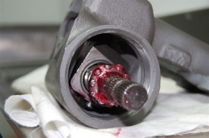
The worm and sector gear is installed with both the inner and outer ball bearing assemblies lubed with Trans-Jel.
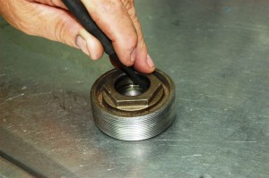
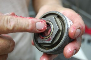
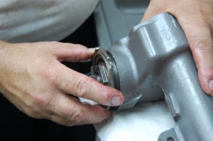
The worm shaft adjuster cap is threaded in to capture the inner and outer bearings. Clean lubricated threads are necessary to properly adjust the worm shaft end-play.
The outer lock-ring is tightened after the end play is set. The worm shaft should have a very slight drag. You should be able to rotate the shaft easily without perceptible side to side movement of the shaft.
We lube the bushings and seals before installing the pitman shaft. The tapered, splined end of the pitman shaft that goes through the lower seal shown should be taped with one wrap of masking tape. The tape protects the seal from damage during installation of the pitman shaft.
The Pitman shaft should be installed with the sector gear centered. This is the ideal location for correct pitman shaft depth adjustment.
Our Overhaul Kit comes with shims to tighten up the adjuster bolt. This keeps the pitman shaft rotating at the same level plane. We selected the shim that fit the tightest without hammering it in.
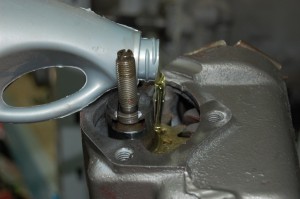
Mobil 1 Synthetic gear oil is used to fill the gear box approximately half full. We found that filling the gear oil to the bottom of the worm gear adjuster plug threads when the gear box is in position on the frame works best. If you fill the gear box completely, there will be leaks everywhere from heat expansion.
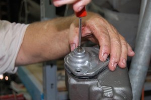
The pitman shaft cover is installed using the screwdriver to lower the cap onto the pitman shaft. As the screw is turned counterclockwise, the cap will seat. Once the cap bottoms on the gear box, turn it a few more turns to make the pitman shaft does not bind when the cap screws are installed.
The cap screws are installed, tightening them a little a time making sure the input worm shaft turns easily. Once the screws are tightened, final torque them to 45 lbs/ft.
Turn the adjuster screw clockwise until the pitman shaft bottoms in the sector gear. Use the screwdriver only. No extreme force is required. Back the adjuster screw out a quarter turn. Install the box and enjoy smooth tight steering!
Story and photos courtesy Chris Petris
I live just outside of Springfield MA. I have a 1962 corvette with a non-operating driver side windshield wiper that needs repair ( wiper transmission, which I have)
I am unable to find any mechanics that are willing to fix the problem. I have called over 15 places, and shops are either overbooked or not interested. Waite time is a year in some shops.
Does this group know of any competent mechanics, in the area of Western MA, that you can refer me to? I have owned the car for 2.5 months now and it will not pass inspection without fixing the problem. Hence, I can not drive my C-1.
John
Can you use synthetic green grease instead of 80-90 gear oil? Was reading on Corvette Forum and that seemed to be the opinion of the comments there. Thoughts?
Extremely helpful article.
My steering coupler pins, hit the safety horns on each side. The steering wheel start to move the wheels upon engagement of the pins, to each side of the safety horns. If I replace the coupler, will this cure this slop?
If you see the safety pins hit the coupler housing while the steering wheel is rotated, the coupler is shot.
Looks very expensive. … What is the total hours and cost for this?
Cost depends on what you may need to complete the job. We do offer a Deluxe Corvette steering box rebuild kit.