
There was a time when a component would fail it would require repair or rebuild. But today we throw it into the appropriate recycle pile. Growing up in the 60s and 70s sometimes makes it difficult to trash anything; today it makes more fiscal sense to buy another one. If you worked in a GM dealership in that time period, the philosophy was repair unless it had catastrophic damage. Of course back then metal was used for most components; plastics were for the occasional trim piece. One of the many repairs you had to perform at the dealership was rebuilding windshield wiper motors, distributors, alternators, starters and fuel pumps.
Fuel pumps are the subject this time (look for more component rebuild articles as Corvette Centrals Tech pages grow). Corvette Central already supplies a factory style instructional page to aid in the rebuild. This article will show more in-depth photos and tips on the process. All of the fuel pumps from 1955-1966 were similar in construction in that they could be disassembled. Later, the upper portion of the pump was crimped to the lower, making rebuilds impossible, at least for the typical shop. To start with, do you really need a fuel pump rebuild? Fuel pumps need to supply high fuel flow especially under wide open throttle conditions. Pressure is required, only enough though, to make sure the fuel flow does not decrease as it travels up to the carburetor.
While we are discussing flow, there are a few facts that you need to know. 1953-1962 Corvette fuel tanks are considerably lower than the top of the carburetor, while the 1963-1967 fuel tank is almost level with the carburetor. The significance? A 1963-1967 Corvette will still run with a failing fuel pump. Gravity does the job of providing fuel to the carburetor which might give you a sense of how flow is important not so much pressure. If you remove the fuel pumps supply hose from an engine that has been running, fuel will flow until the tank is dry due to gravity and the siphon effect. Carburetors use needles and seats to control fuel flow, stopping the fuel when the engine is shut down. When the engine is running, they also meter the fuel flow rate as the fuel level changes during acceleration. Now that we know how gravity and tank versus carburetor height affect fuel flow, having a good sealing carburetor needle and seats are a must.
In the past, I have had to drain a customer’s engine oil because their carbureted engine had leaking needles and seats that control fuel flow in the carburetor. The leaking needles and seats filled the crankcase with fuel. In one situation, a big block mid-year had been jacked up at the rear for other repairs, almost draining the fuel tank into the crankcase. Luckily the owner noticed what they thought was a major oil leak that had developed before trying to start the engine. When the oil was checked, it looked like water was running off the dipstick. The crankcase also appeared to be way over full. They put two and two together when they noticed the fuel tank was empty. This could have been catastrophic had they tried to start the engine, possibly damaging the engine bearings or bending a connecting rod from hydraulic lock.
Now we know that the 1953-1962 will possibly start, but not run for long, while a mid-year could possibly ease down the road on a failed or failing fuel pump. If your early Corvette has no power and feels like it is running out of gas, chances are the fuel pump is the culprit. Fuel pumps are simple devices with two check valves, one to allow fuel in one to allow fuel out and a diaphragm to move the fuel. Check valves are one way devices allowing flow in one direction not the other. When a check valve fails, the diaphragm pushes and pulls fuel through the same check valve, negating the pumping of fuel. The typical check valve failure is from debris that is flowing from the tank or through the fuel lines. Corvettes that sit around for months at a time are most susceptible to this, as rust and scale forms in the lines and tank.
You can test your fuel pumps operation with a vacuum gauge, installing it on the suction side of the pump to see if it is obtaining vacuum. Depending on how long you crank the engine, you can see as high as 10-15 inches on a new pump with tight check valves. If the suction side check valve is good, it should also hold vacuum for3- 5 seconds after cranking the engine. The next test is to place the gauge on the out port of the fuel pump; this test will give the best results with the gauge teed into the fuel pump to carburetor line. If the engine runs, that is even better. Start the engine and watch the gauge. You should see three to four pounds of pressure at idle. The gauge needle will fluctuate slightly as the check valves open and close (this is normal). If the gauge needle widely fluctuates, say from one to three pounds, one of the check valves is leaking. Pump performance will be poor, especially when you need fuel the most under hard acceleration. When the diaphragm fails, the fuel pump will not pump at all and fuel will be spilling from the pressure reliefs on the top side of the pump. Either way, the pump will require a rebuild.
Fuel quality also plays an important role in the life of the fuel pump and carburetor. Many early Corvettes are subjected to water in the fuel from long periods of sitting in humid conditions. Is ethanol the culprit? Ethanol does not appear to cause long term damage as long as the fuel is used regularly; the jury is out though on what happens if the fuel sits for years at a time. I have seen firsthand what happens when copious amounts of water are left in carburetors and fuel pumps. The metal alloys begin to grow as the corrosion forms, causing flaking and complete destruction of the components. The 400 horsepower 1967 that I spoke of earlier had total destruction of the carburetors and fuel pump from water in the fuel. This was a Corvette that had never seen ethanol fuel either, for many years it sat in a garage in Florida without ever starting. I became involved after the owner had tried to get the 67 running after the fuel in the oil incident. This project required a Corvette Central complete fuel tank package, new carburetors, fuel pump and replacement fuel lines. That meant to do the fuel line job, the body required raising enough to access the rear of the line where it passes through the frame rail. So… keep clean fuel in the tank.
Let’s get going on the rebuild now that we know if we need to or not. For those wanting an original exterior finish, do not sand or bead blast the pump. Stainless steel brushes work best, preferably softer bristles for the final brushing. This will remove the typical corrosion while preserving the original look. The accompanying photos will show the process from beginning to end. Before disassembling the fuel pump, either mark or make a note of the positioning of the upper and lower fuel pump housings. There are multiple positions available that the lower housing can be placed in; only one will allow proper fuel line and suction hose connections.
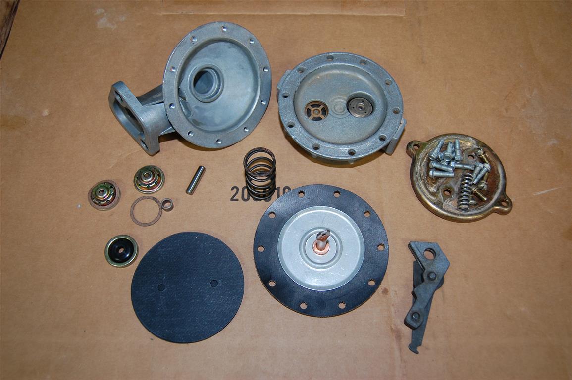
The typical 1955-1966 fuel pump will look like this once disassembled with the Corvette Central supplied fuel pump rebuild kit (kits available for 1955-56 for 4150 or 4262, 1956-57 for 4346. 1958-65 for 4445, 4656 and 4657, or 1964-66 for 350HP, 365HP, 375HP #40083) . The fuel pump halves have been cleaned with a stainless steel brush and the lower cover also lightly brushed to avoid removing the plating as much as possible, that would allow more corrosion to occur. This is a 350 horsepower pump with the two additional screws on the lower cover.
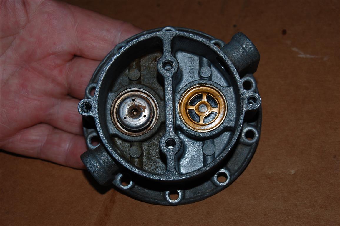
These are the old check valves in place ready for removal. You can see the discoloration from water laden fuel in the out portion of the fuel pumps lower housing. This is the time to make note of the check valve orientation, not all valves look alike. If the valves are inadvertently installed upside down the fuel would be drawn out of the carburetor and pushed back to the tank.
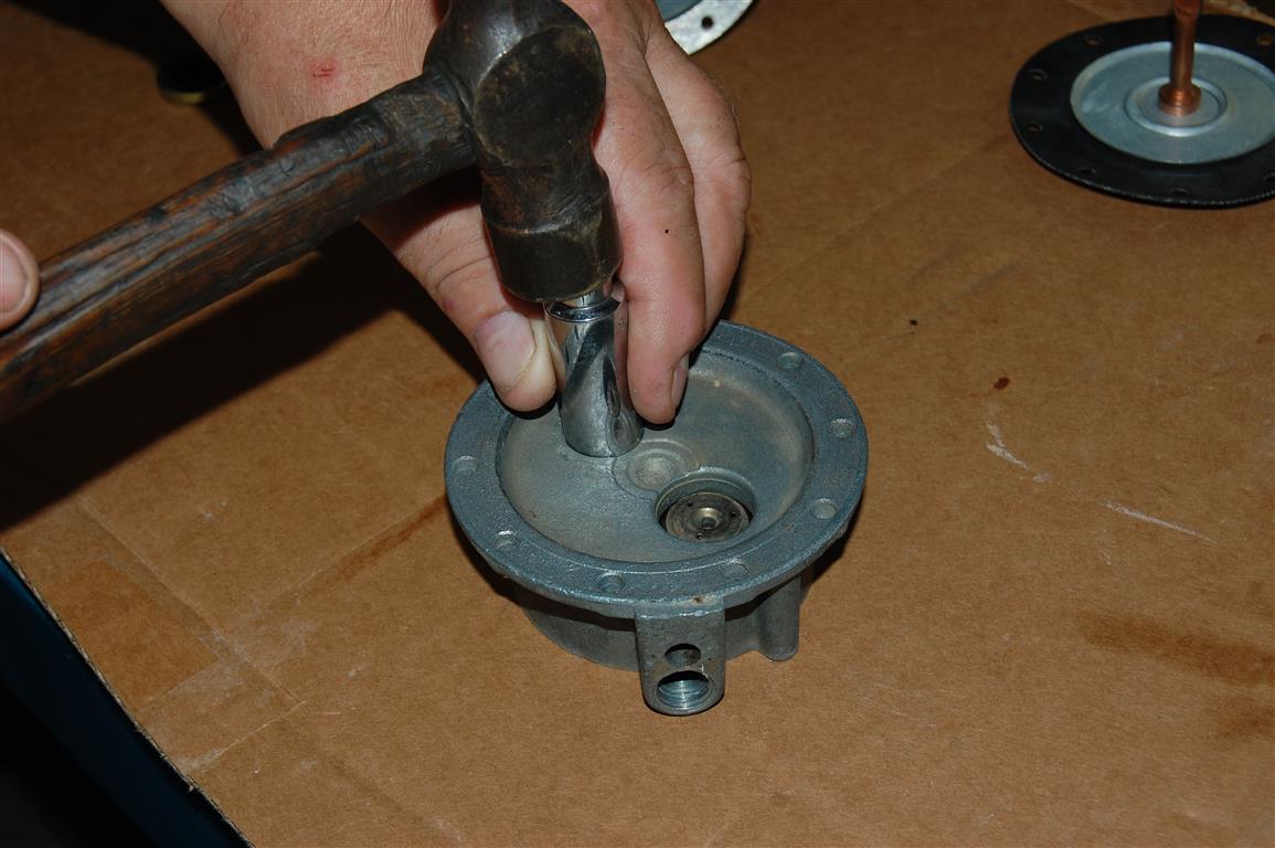
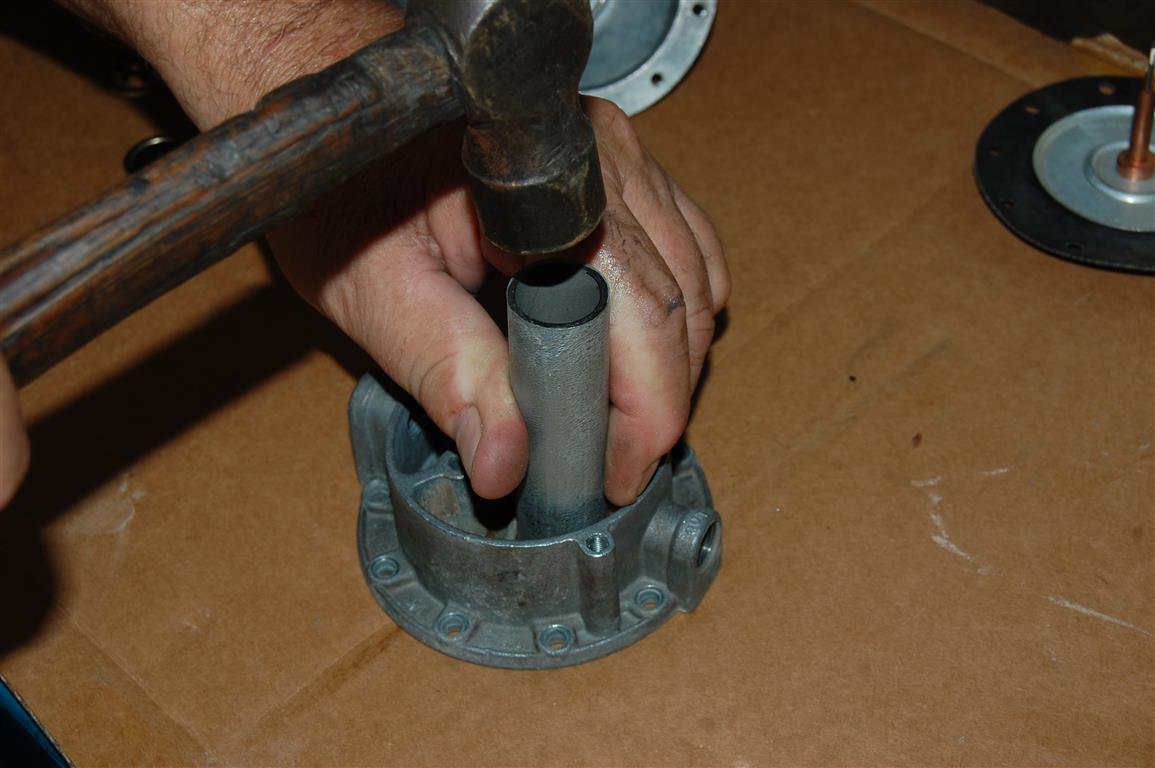
A socket works best to knock out the old check valves, again note the valves positioning.
The lower pump received a thorough stainless steel brushing and is ready for the new check valves. The supplied gaskets are an important part of making sure the check valves do their job properly.
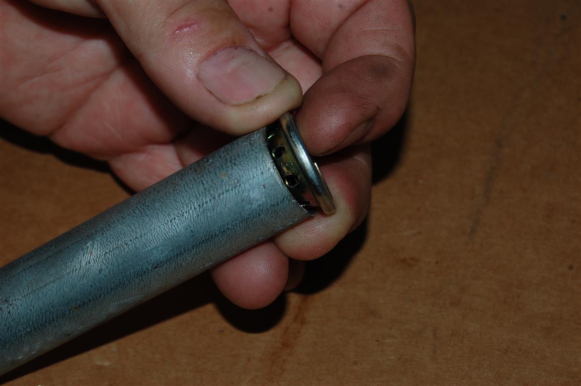
I use a piece of ¾ EMT thin-wall electrical tubing to install the out check valve into the lower housing. The important thing to watch for is check valve cover damage during the installation. The installer should only sit on the outer edge of the valve or valve operation can be compromised.
The tubing is used to seat the valve after the gasket and valve are installed.
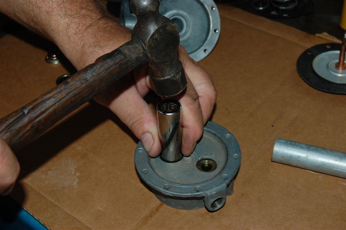
On the in-side of the fuel pump lower housing a 5/8 inch socket is used to seat the check valve. Like the out-side check valve in the pumps lower housing this check valve should not be touched except around the outer ring during installation.

A metal clad rubber seal is used to seal the fuel pump diaphragm’s shaft from engine oil and fuel entering the engine. These seals often come loose or leak. I use naphtha to clean the seal area before the sealer is supplied.
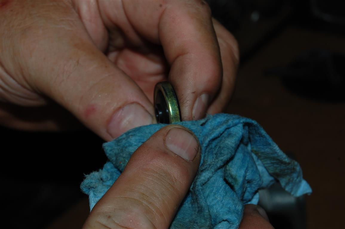
The same naphtha cleaner is used to wipe off the seals metal surfaces before installation. This is the difference from a quick throw-it –together rebuild or a professional rebuild that considers and handles all the possible issues that can occur.
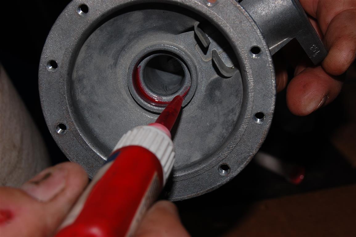
Red Loctite is used for complete sealing and making sure the seal stays put in the upper housing. The diaphragm return spring sits in the pocket around the outer edge of the seal so it will not fall out. The objective is to make sure it seals. As the seal moves around from the constant spring pressure, it eventually begins to leak unless it is securely installed.
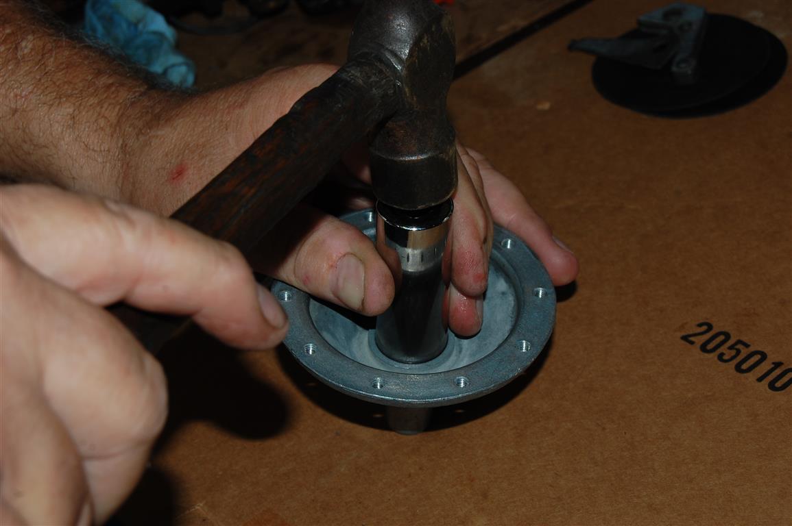
Like the check valves, be careful when seating the diaphragms shaft seal. The socket should fit the outer ring without hitting the rubber inner seal.
High temperature chassis lube is applied to the seal for assembly.
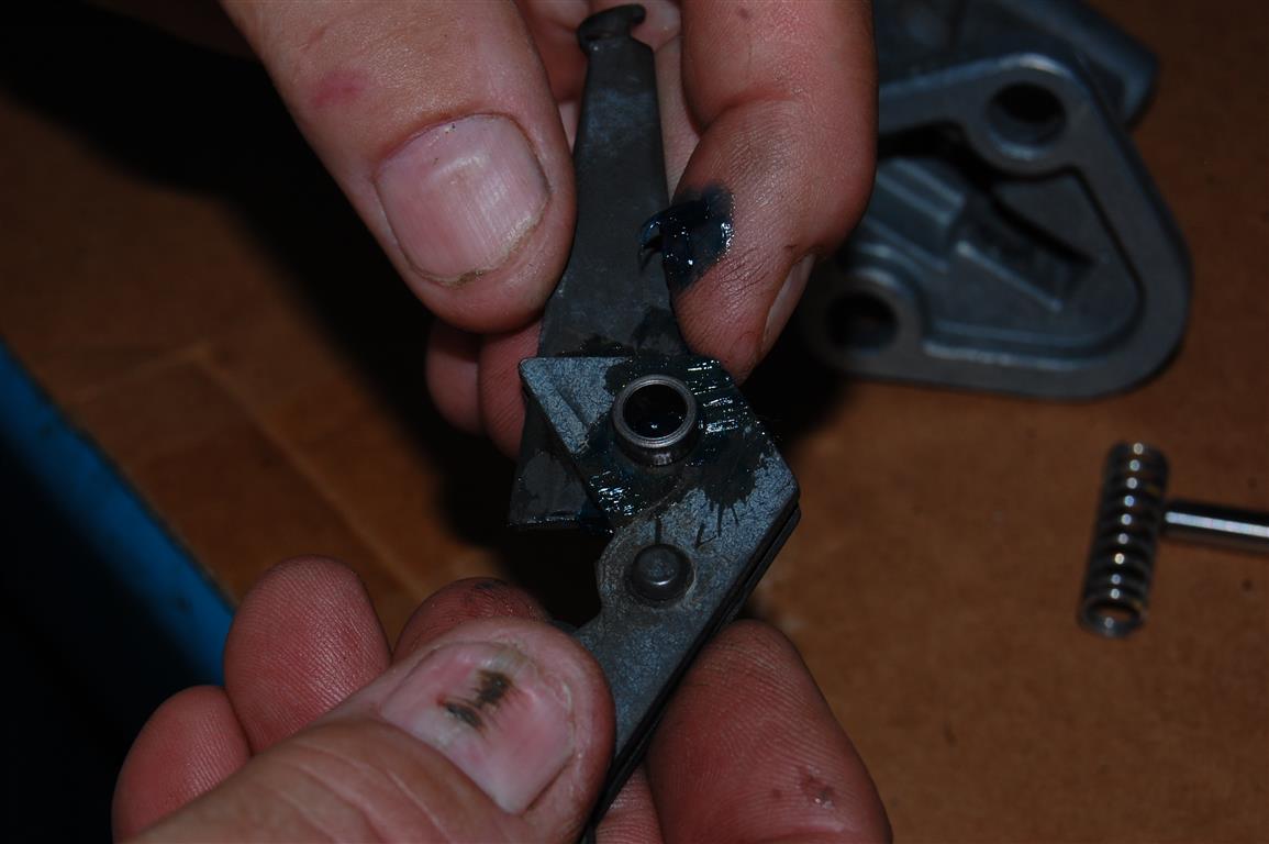
The next step is to assemble the actuator lever assembly with the sleeve connecting the two pieces. Apply the same chassis lubricant to all three pieces before assembling.

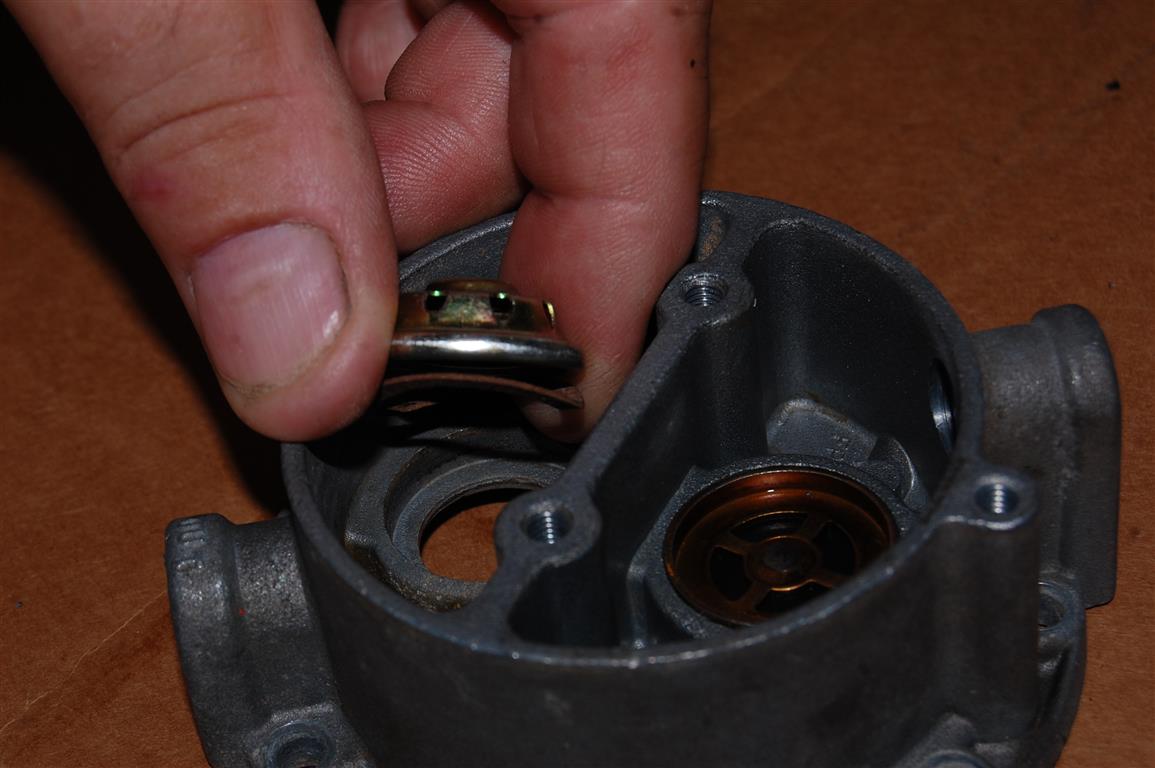
The new diaphragm is installed with the supplied return spring. You must orient the diaphragms actuator rod shafts slot to allow the actuator lever to grab the shaft. The tricky part is about to begin: the actuator lever assembly must be installed blindly into the diaphragms actuator shaft slot.
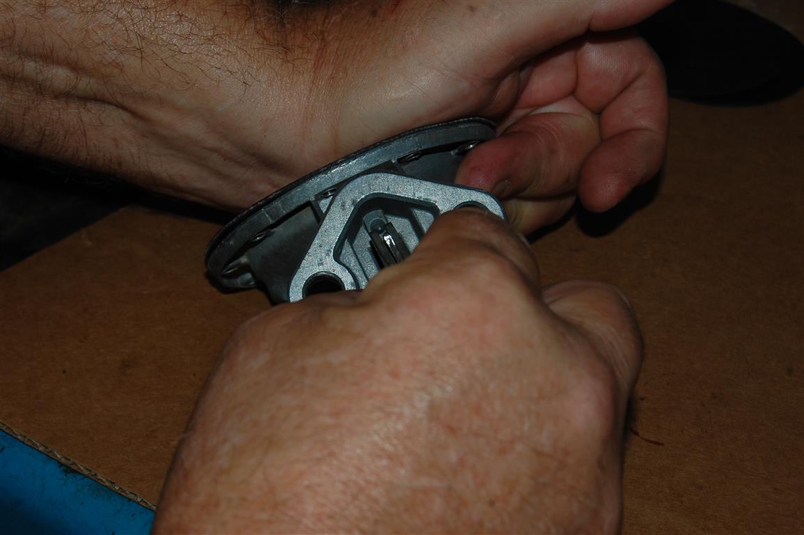
My big hands are hiding some of the contortions that are taking place. The diaphragm is pushed inward as the actuator lever assembly is hooked into the diaphragms actuator rod slot. This may take a few attempts to accurately make the connection, once done properly the diaphragm will stay in place. If it pops out, the rod was not hooked properly.
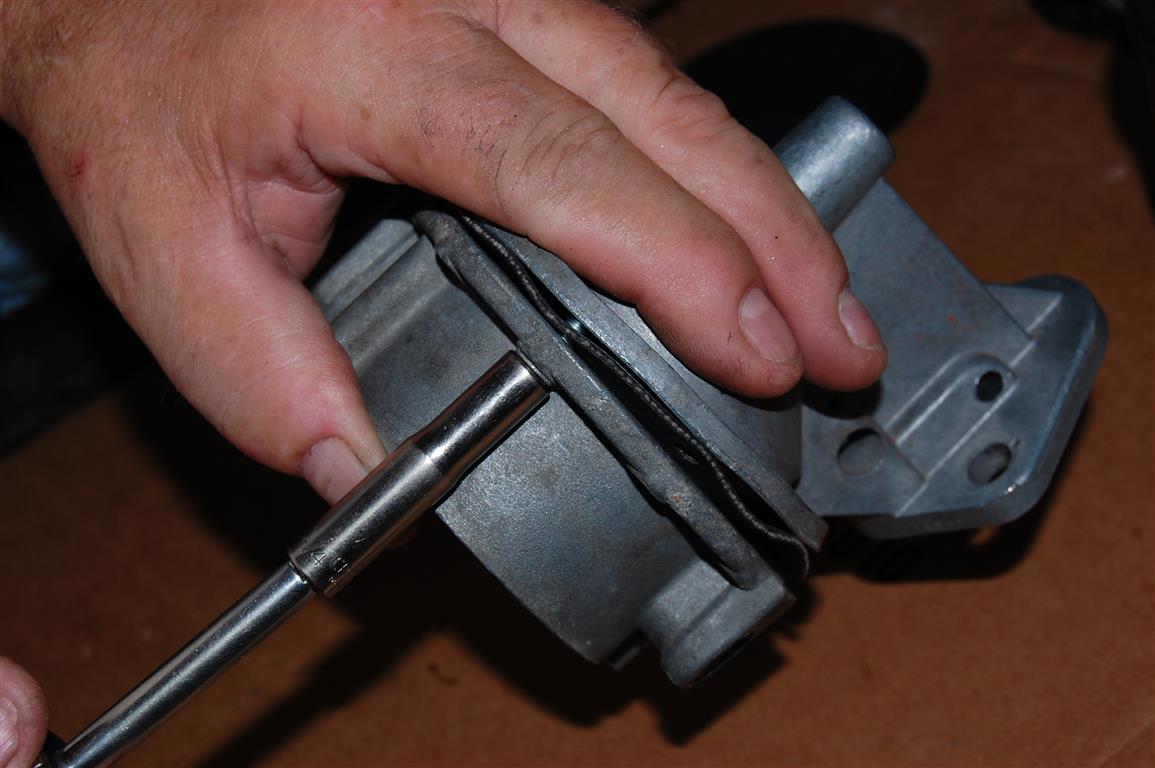
Before installing the actuator lever assembly pin, I install the lower fuel pump section to take tension off the diaphragm during the pin installation. One important note: you must orient the lower fuel pump housing correctly for fuel inlet and outlet fitting positioning.
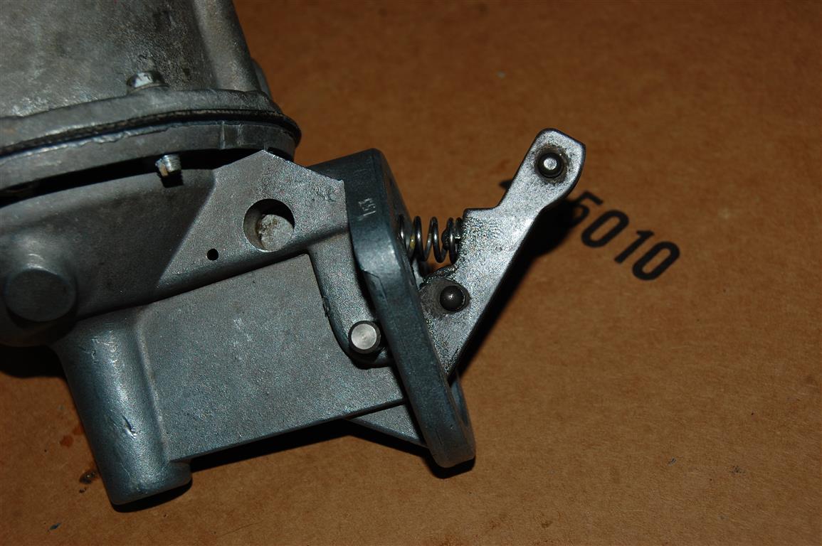
The actuator lever return spring is installed while the pin is pushed into place. I push the pin in until it just begins to go into the other side of the upper fuel pump housing.
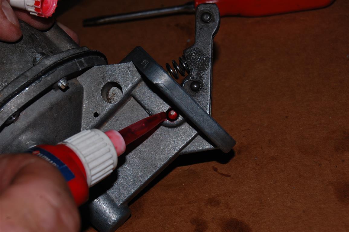
Over time, the upper housing wears where the pin is seated. Applying red Loctite assures that the pin will not back. The Loctite is applied to the side with the pin partially installed, then the pin is pushed into place from the other side. To assure that the pin is secure, I push the pin further through the side that the Loctite was applied. This allows application of Loctite on both sides of the fuel pump housing. Once both sides have Loctite applied, the pin is centered in the upper fuel pump housing.
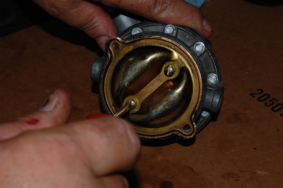
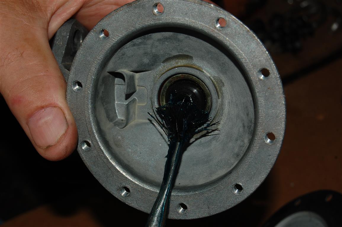
The wrap up requires the installation of the lower cover. This cover was designed for fuel pump repair. Fortunately, it also allows a periodic check of the fuel system. If the fuel tank has dirt, rust or any debris it will end up being drawn into this area.
Story and photos courtesy Chris Petris
First of all, this is a great tech article! I’m wondering if you have any knowledge/experience with the more modern-day (but now obsolete) AC #12355612 long screw fuel pump. Appearance and specification-wise, it is identical to the ’56-’57 Corvette pump (4346). I want to rebuild my #12355812 and need a rebuild kit do to so. I would appreciate any information/kit that you can provide.
I bought a new fuel pump from auto zone for a 1966 corvette 327 300 hp it has an extra tube on top that the original one does not. Can I just plug it or does it have some other function?
You’d have to ask the manufacturer of the fuel pump.
Its simply a vent tube to relieve upper chamber pressure, (the origanal had holes) leave it open
What should fuel pressure be on 375 hp FI unit where can I find a. 4657 fuel pump
The 327/365 – 327/375FI. engines used a higher pressure pump, 6.5psi-7.5psi. and sorry we do not have any leads on any fuel pumps at this time.
The answer to the pressure is in the title of the article to which you link here – 6.5-7.5 Psi.
I have no idea where you can get a pump.
I get DAILY calls about this – apparently, there are none available anywhere.
Regards,
Gus
Corvette Central Product Assistance
Great article. thanks.
My pressure test ps seem fine in and out. How can I test flow “volume” and how much should I expect from an AC model 4445 on a rebuilt 283 with 2 4s. ‘58 vette.
Thanks
Hello
Need packing set for fuelpump öre new
Have stingray 65 with turbo jet bigblock 6500cc
Can you help?
Thanks so much for this post. I had purchased a new fuel pump for my 1966 small block Corvette and just wasn’t getting fuel to the carburetor. With the provided guidance in your photos and text I was able to disassemble the new fuel pump to find the actuator lever had become disengaged from the diaphragm shaft. Successfully rebuilt/reassembled the “factory new” pump and now car is running like a dream. Would not have had the confidence to attempt the fuel pump reassembly without your help.
I have a 65′ 327 300 HP that requires me to crank the engine excessively before the engine starts, ONLY after setting for several days. The engine will start normally if it sets over night or extended period during the day. A mechanic suggested this could be caused by a leaking check valve in the fuel pump, or possibly by the (original Carter AFB) carb leaking fuel from the bowls. I had the AFB rebuilt about seven years ago and it did not effect the starting problem. I have not noticed any apparent fuel delivery or performance issues with the engine. I’d greatly appreciate your thoughts before rebuilding the fuel pump. Nice Article.
George,
Based on the symptoms, I think the fuel is evaporating or leaking out of the carburetor float bowl.
Once fuel passes the inlet valve in the carburetor the pump is out of the picture, Fuel cannot siphon back out of the carb.
Gus,
Corvette Central Product Assistance
Hello –
I ran across you post while researching the diaphragm shaft seal for an AC mechanical fuel pump on a ’63 SIIa Land Rover (2.25 liter, 4-cylinder gas engine).
The shaft seal is similar to the one you have, I think the one on mine is a little thicker. It also sits in a “cup”.
For some odd reason I can’t find a replacement seal. The seal does come in the kit that contains the diaphragm pushrod that has the hole in the end. Mine is the style that looks more like a keystone, evidently they don’t provide the seal in these kits. Do you know of anyone who sells these seals?
The seal currently in mine looks decent, no sign of tears or cracks and it still feels pliable when you touch it. If I can’t find a replacement, do you have any advice on how to improve the one already installed?
Thanks for your time and help.
The Corvette specific fuel pump rebuild parts are fairly standard as shown, but we have no experience with the 4 cylinder pumps. Unfortunately, I don’t know who would have these or what would be needed for use in this application. Maybe some of the Land Rover forums would have information on this.
do you have an article on rebuilding a 1953 corvette AC9797 fuel pump. or where I can get instructions? Thank You
Unfortunately, this is not something we have an article on. I do not have instructions for this, but you could possibly find it in a passenger car service manual for 1952-1954.
do you Loctite the rubber seal or just the metal cup the seal sets in thanks
I recently got my 63 vette back on the road and after a carb rebuild and a tune it works fine accept for when I get off the freeway it will not idle and cuts out at the end of the offramp, if I goose it a bit while coming off the freeway and keep the RPM up for a minute it will come back and stay idling. the pump has not been rebuild and is the old original pump, Is my issue related to not having enough gas in the bowls and a rebuild of the pump will do the trick or? thx
I would recommend having it diagnosed by a certified Corvette technician.
I had the same problem with my 1966 corvette. I tried replacing the fuel pump, insulating the fuel line, timing adjustment, carb adjustments and nothing worked. I then noticed fuel dripping from the secondary’s sometimes when at idle. I lowered the float on the secondary by sloshing fuel out of the sight screw and then lowering the float per Holley web page. Problem solved. It also dropped my running temp 15 degrees and lowered my exhaust gas smell.
I rebuilded my fuel pump (4657 DF) based on the Corvette Central parts and this excellent article. Everything went well but I am not satisfied with the pump performance. I measured pressure and vacuum of the (not installed) pump with a gauge. The pressure and vacuum levels are constant during a long period of time so the check valves should close correctly. But the pressure reaches only about 3 pounds (should be at least 4 pounds). Do you have any suggestion how I can rise the performance of the pump?
I’m not aware of a way to rise performance of a pump and I do not know of any rebuild kits that produce more PSI. We sell many #351316 rebuild kits without issue. 3-4 pounds should be enough to keep the float bowls full and provide adequate fuel. As long as the kit is installed properly and the pump is operable it should get the proper volume to run the car.
Fuel injection an hi horse motors need 5 to 7 pounds.
The large spring on the diaphragm is what controls the pressure. The spring is weak and requires replacement. I have a spring force gauge and I checked two of my springs. The original at 16 pounds @ 1″ and the one that came with the kit at 20 pounds. So they do vary.
My 64 Vette stopped running, definitely a fuel issue. I replaced the fuel pump 2 years ago and rebuilt the carb from sitting. Car ran great then “poof” just stopped running while I was pulling in garage. My question is, should you see fuel flow if you disconnect the fuel line at carb and have someone crank the motor? Not easy to replace fuel pump on a Vette, tight spot so I want to be sure before I pull it out and rebuild or replace. Could the accelerator pump be the issue? Thank you.
You can test your fuel pump operation with a vacuum gauge, installing it on the suction side of the pump to see if it is obtaining vacuum. Depending on how long you crank the engine, you can see as high as 10-15 inches on a new pump with tight check valves. If the suction side check valve is good, it should also hold vacuum for 3- 5 seconds after cranking the engine. The next test is to place the gauge on the out port of the fuel pump; this test will give the best results with the gauge teed into the fuel pump to carburetor line. If the engine runs, that is even better. Start the engine and watch the gauge. You should see three to four pounds of pressure at idle. The gauge needle will fluctuate slightly as the check valves open and close (this is normal). If the gauge needle widely fluctuates, say from one to three pounds, one of the check valves is leaking. Pump performance will be poor, especially when you need fuel the most under hard acceleration. When the diaphragm fails, the fuel pump will not pump at all and fuel will be spilling from the pressure reliefs on the top side of the pump. Either way, the pump will require a rebuild.
I recently did a fuel pump rebuild with the help of this article. It worked great and is now pumping gas as it should. One question, though. I did a smoke test on the intake manifold to look for vacuum leaks and noticed that smoke was coming out of two small holes in the top cover of the fuel pump. Is this normal? Thanks for any feedback.
Yes, the cavity is not sealed so it is possible for smoke to make it down through the block and into the pump opening, then find its way out the top.