The radiator core support has two functions: radiator placement and front end support. Weakened core supports allow the nose of your Corvette to droop, increasing the gap between the upper part of front fender and the door. When that occurs, stress is placed on the inner fenders. Before the core support project begins, a thorough inspection of the attaching hardware and cushions is in order. We’re working with a rough but fairly original car, so we were careful to save the hardware and as many O.E. pieces as possible.
When you’re ready to purchase the core support, there is one steadfast rule – always measure the core width. It doesn’t matter if it’s a small-block car with an aluminum radiator or a big-block midyear, always measure the core. The distance is measured from tank to core raised ribs; once you receive the core support, check it for proper radiator bracket support spacing. Late ’76-’82 core supports use clips to retain the shroud at the bottom, while earlier cars have brackets and nuts. If you have ever replaced the upper control arm bushings, you know how exciting it is to remove the radiator shroud. This is your chance to do the upper control arm bushings if necessary and a great time to check integrity of the radiator.
After doing this type of work several years, you learn what may seem like a shortcut can take an exorbitant amount of time. Instead of fighting with the radiator and shroud, we removed the hood and core support mounting bolts to allow room to move things around before removing the radiator. It may seem like extra work, but your sanity remains intact and less damage occurs. This is a major concern when dealing with this 427 Corvette since the radiator shroud can’t be replaced with a NOS piece easily. Handle it carefully, or pay the price.
Radiator seals are often neglected but play an important role in keeping your Corvette cool at highway speeds. Forced air takes the path of least resistance and if the radiator isn’t sealed to the support, the much needed air flows around the radiator, not through it. Along with the core support, plan on installing correct seals. Watch carefully when ordering because there are many variations of seals used.
While the radiator was out, we had it checked for leaks and any coolant flow restrictions. We were fortunate that the radiator had been replaced recently, but it was a shame to put it in that terrible core support. The radiator pressure tested fine and had good flow. Copper radiators utilize solder to retain the tanks to the core, and they have a tendency to corrode from impurities in the solder and the soldering process. Look closely at the soldered seams for corrosion; if any are found, the radiator should definitely be sent for repair.
If you have A/C, check the condenser for corrosion on fins or smashed fins restricting air flow. The A/C condenser can stay right where it is during the core replacement. At the very least, use compressed air to blow out the debris towards the front of the car; you’ll be surprised how much you find.
This is one of those two-weekend projects: removal and disassembly procedures, then cleaning and prepping all week. The install job isn’t too bad when everything is cleaned up. Here’s how to do it.
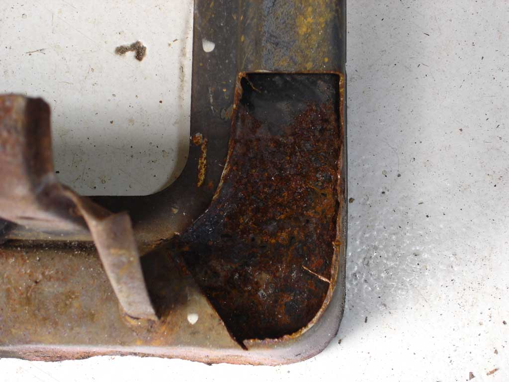
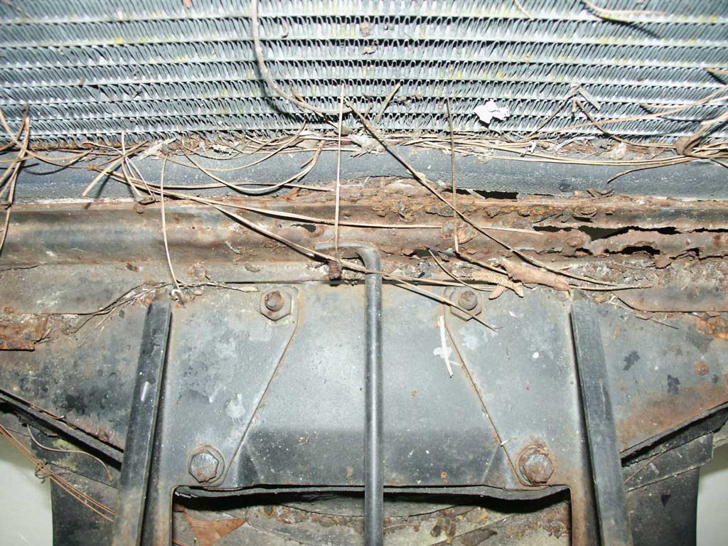
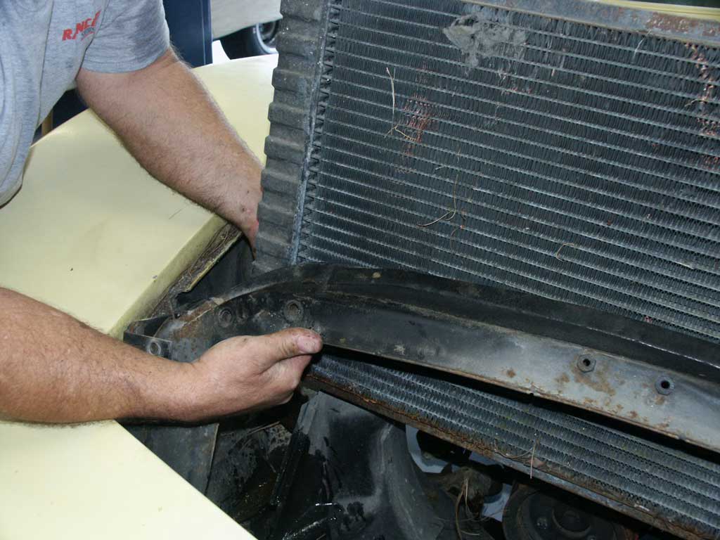
The core support looks good until you take a close look at the base of the unit. We thought we could fix the corroded areas with a patch panel until we cut the offending pieces out. The inside was much worse than the exterior.
Mark the hood position with a scribe; this will simplify the hood installation. The front end was sagging from the rotted core support; the new support will relieve the load off the upper part of the fenders. There was no radiator seal remaining across the top of the radiator and core support.
With the hood removed, start on the upper and lower hoses. Remove the hoses completely to allow as much room as possible. This is one of those jobs you ask yourself where to draw the line. Everything you touch seems to be connected or related to the task at hand. The lower hose is a bear to do with everything in place so now’s the time to replace it.
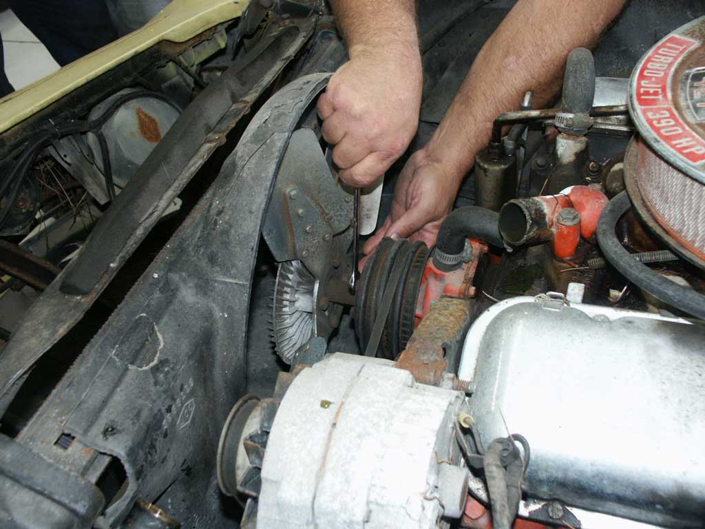
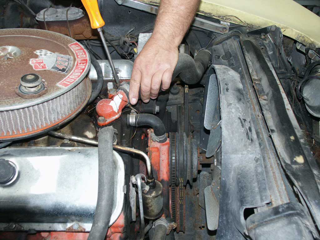
Remove the cooling fan to prevent radiator damage and check the fan clutch for leakage and resistance while turning. Someone had changed our fan clutch to an aftermarket centrifugal type that will be replaced with a thermostatic type. We knew we had a centrifugal fan because there was no thermal spring on the front face of the fan clutch. Thermostatic clutches lock in when they detect heat coming through the radiator; centrifugal clutches lock as RPM increases, wasting energy.
We loosened all the fan shroud upper retainer bolts first and then removed them. If the bolts are stubborn, the fan shroud could be damaged.
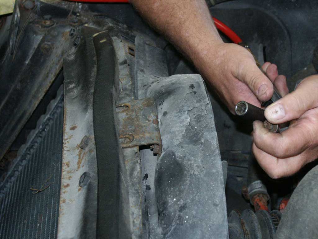
We’ll remove the upper radiator brackets with the impact wrench to save trouble later. The bolts that hold the brackets are different lengths and can puncture the radiator if installed in the wrong location.

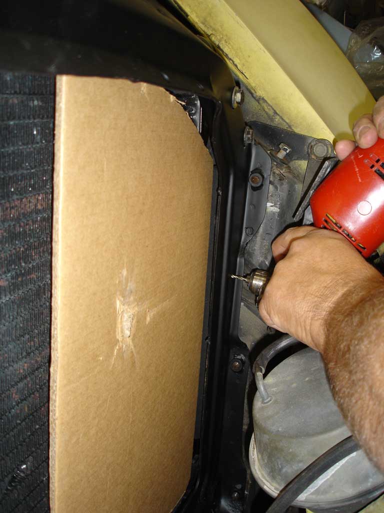
The hood hinge bolt must be removed or loosened enough to allow removal of the core support side upper mounting bolts. If the other hood hinge bolt is left tight, no hinge alignment adjustment will be necessary during assembly. This is where an impact wrench can save you some aggravation. The hammering action of the impact wrench breaks the bolt loose instead of shearing it off. Of course restraint is necessary; don’t put the impact wrench on maximum power and hold it wide open. Let the impact wrench gently slug the bolt until it comes loose.
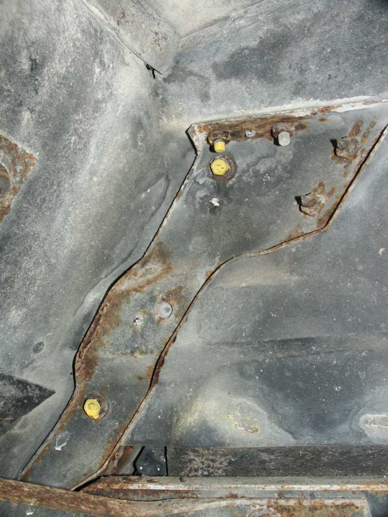
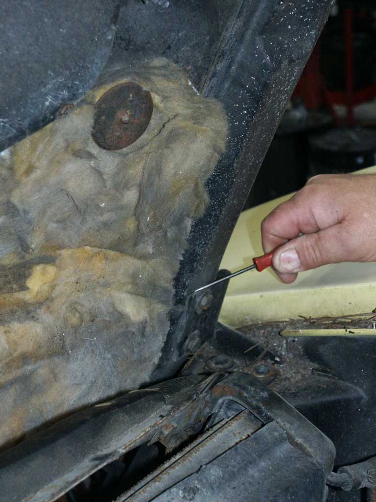
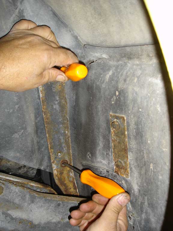
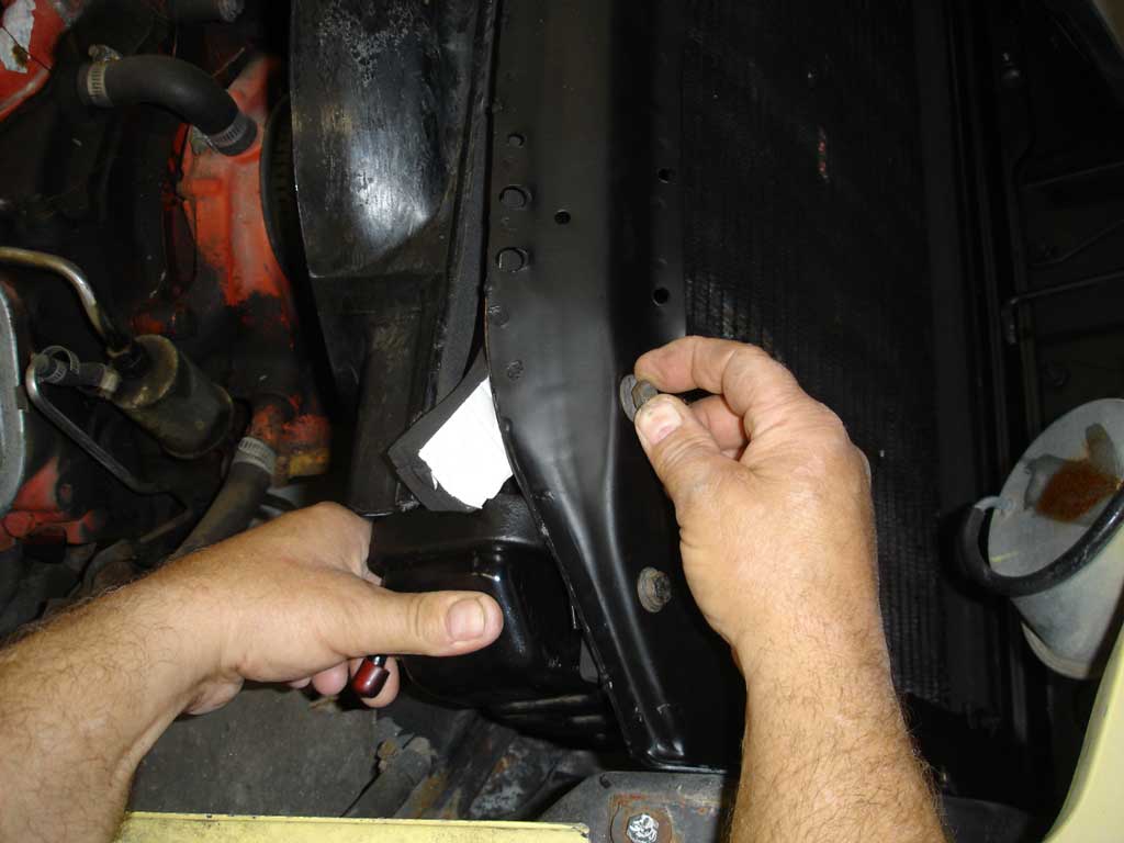
The bolts with yellow paint are the core support to fender mounting bolts. We put some yellow paint on the threaded portion of the hood hinge mounting bolt showing that it’s in the way of the upper support bolt. There is also a lower bolt (not shown) on each side of the core support that must be removed. Wear protective eye wear; dirt comes at you from all sides during disassembly.

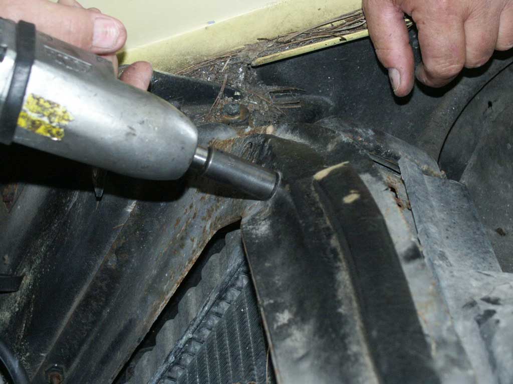
Here’s where the impact wrench really pays off. These lower bolts to the core support can be very difficult to remove. You can apply penetrating oil to the threads but it usually doesn’t help. The threads are bulging with corrosion and need heat to knock off the corrosion for easy bolt removal.
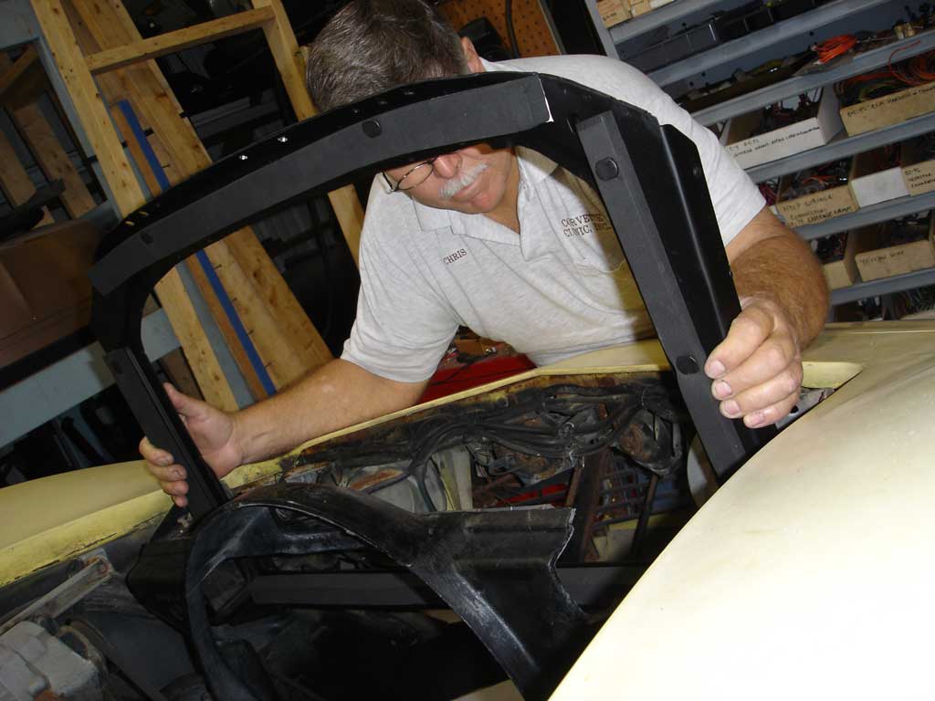
The shroud remains in place while pulling the radiator up and out. We pulled the core support towards the front of the car, as close to the headlight actuators as possible. We had less aggravation because there was no A/C condenser to deal with. The A/C condenser limits forward movement and you can damage the condenser fins if a lot of pressure is applied.
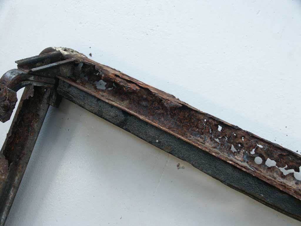
This is an extreme corrosion problem. Unfortunately, the sagging core support did increase the door to upper fender gap on the passenger side of the car. With a little luck and everything back in the correct position, the gap will slowly close up. This may sound extreme, but it also attributes to water leaks in the car. The pressure pulls on the rivets that hold the upper fender retainer plate on the firewall, eventually allowing water to leak in through the cowl area.
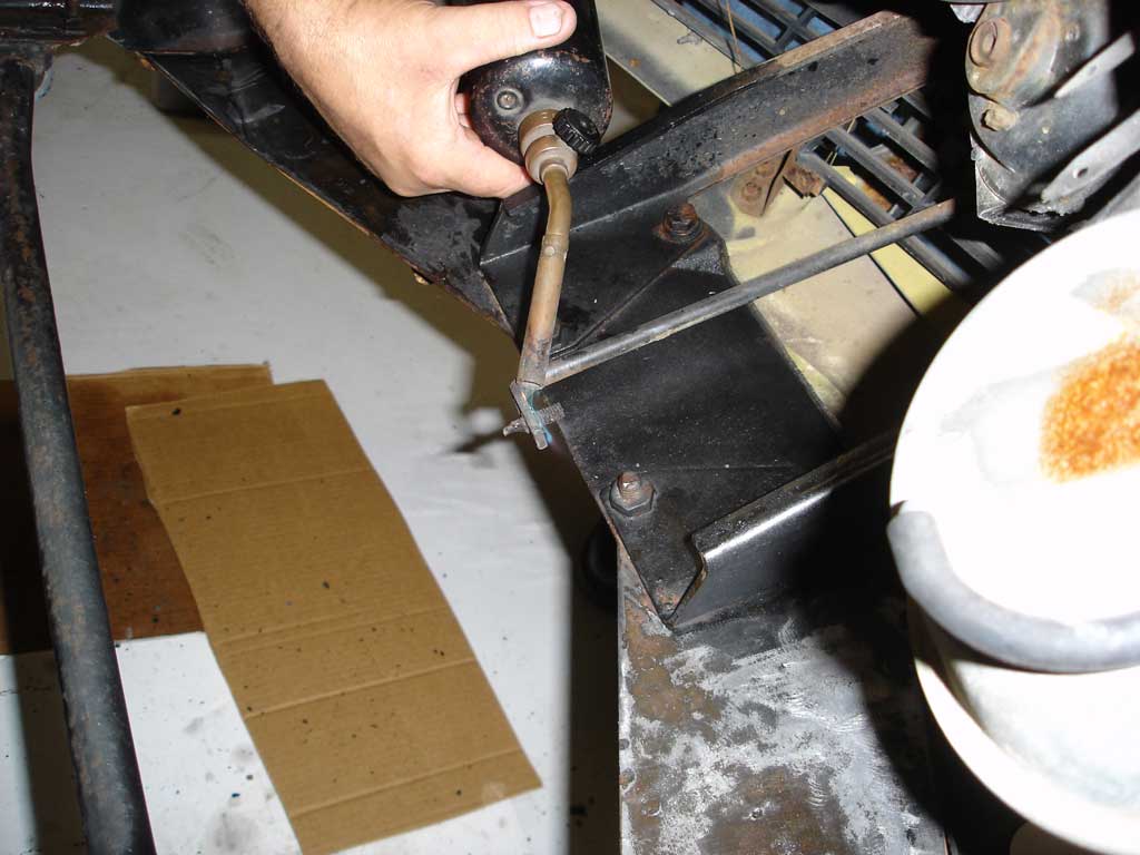
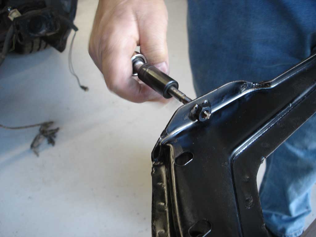
Now that everything is exposed, we can remove the broken brace bolt. As we said earlier, heat is the only remedy when extreme corrosion takes over. Once the bolt was removed a 5/6-18 tap was run through the threads to clean them up.
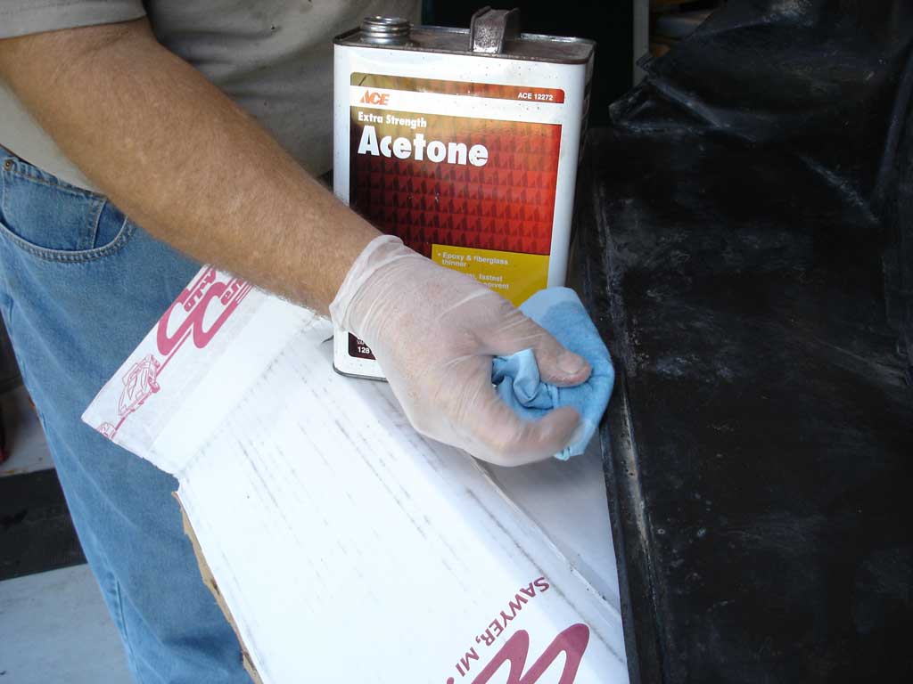
Use acetone to clean the seal surfaces. Wear gloves. Acetone is tough on the body and burns pretty good when it gets in a cut. Wipe all areas that the seals adhere to, including the core support.
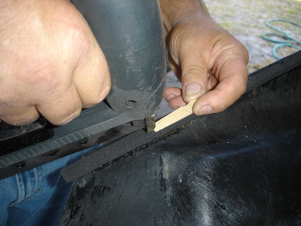
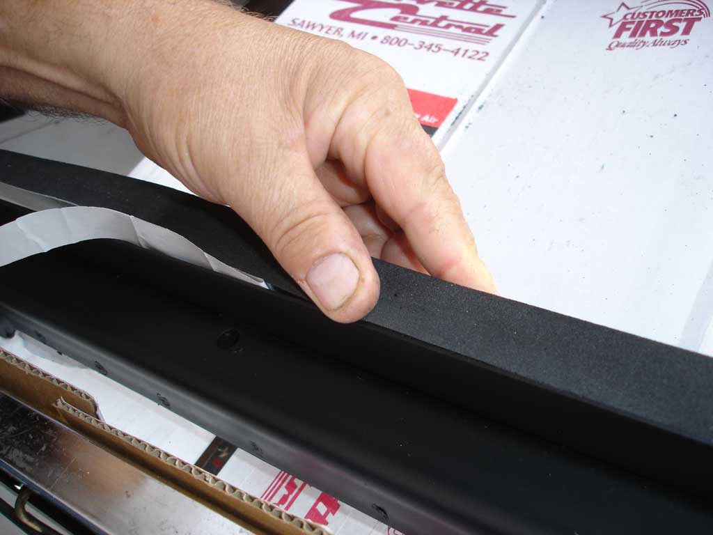
We removed the protective covering from the two sided tape then carefully laid it onto the fan shroud. Sears Craftsman has an electric staple gun with the same reduced-size staples as the O .E. pieces. We carefully installed the staples using a wooden clothespin to back up the safety mechanism during stapling. Without the clothespin backup, the 5/16-inch-long staples went in too deep.
Even though we had a new-old-stock core support, all of the threaded holes had a tap run through them. A 5/16-18 tap is used for the side mounting holes and a7/16-14 tap for the bottom holes. A few minutes at the bench can save a lot of aggravation during assembly.
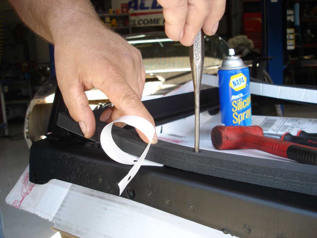
It’s much easier to install the radiator to core support seals on the bench. We use a 1/4-inch pin punch to line up the seals and then pull back the protective paper and stick it down. The seals were fresh and the tape was working correctly. Old seals have a tendency to bunch up the two-sided tape and don’t stick well.
We were working with a late ’69 car, which means push-in fasteners are required. Stick them in the previously lined-up hole and give them a tap with a light hammer. The push-in fasteners slide in as pressure is applied to avoid radiator damage. The fasteners can be left off, but are correct on late ’69-’79 in most applications.
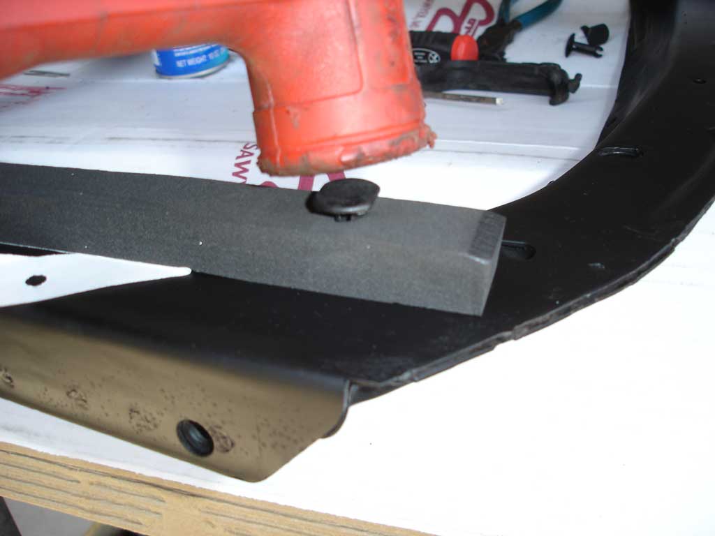
Watch the placement of the lower seal. It goes on the outer edge to seal properly to the radiator. Install the radiator with the core support on the bench to make sure the seals are installed correctly and doing the proper sealing job.
Install the fan shroud first. The shroud will not drop into place in one piece after the core support and radiator are installed. Lay the shroud on the frame where it sits normally. Then, set the core support with all the seals installed into place.
Once the radiator is dropped into place, line up the core support side, center and upper screw holes. Use two Phillips head screwdrivers to line up the core support to the inner fender and then remove one of the screwdrivers to install the 5/16-18 screws. Don’t tighten anything until all of the side screws are started.
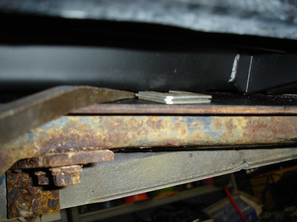
We counted three shims between the core support and the front crossmember during disassembly and installed the same amount. Install the correct 7/16-14core support to crossmember bolt and use a short pry bar to raise the core support and install the shims around the bolt.
We left the protective covering on the two-sided tape on the passenger side so we could install the upper radiator bracket and then stick the seal to the inside of the bracket. The seal is captured between the radiator and the upper bracket. Sticking the seal to the core support first makes bracket installation very difficult.
It would have been much easier to drill the hole for the ground wire with the support on the bench. The ground wire prevents static electricity and electrolysis. The ’63-’67 horn relay will be inoperable when the ground is left off.
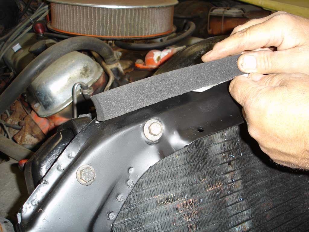
Install the air dam seal on top of the core support. The air dam seal keeps air from flowing over the top of the radiator. It sticks in place with the two-sided tape; no push-in fasteners on this application.

The condenser mount consists of a rubber grommet with a steel sleeve. The grommet is captured in the mounting hole then the sleeve pushed into it. We used fender washers to properly secure the mount. We put a washer on the inside to prevent collapsing the core support.

GM was nice enough to leave the bottom condenser mounting tab open. This allows you to install the condenser rubber mount and sleeve on the core support and then slip the A/C condenser in place.
Story and photos courtesy Chris Petris
Super excellent instructional. You are a huge credit to the hobby of classic vettes and I really appreciate it. I have been observing my 1968 327 350 hp very since I bought it 2 years ago. Initailly I thought it was completely rust free as far as ‘holes’ and ‘pitting’ and only had minimal ‘surface’ rust. After crawling around it without a lift available I have found the radiator support and rear frame crossmember had more rust. The crossmember has some minimal pitting as does the extreme rear 18 inch’s of the frame. I do ‘t want to disassemble any of this bit it is presenting a good bit of difficulty laying g on the floor and doing this ‘project’. The core support has a small rust hole area around in or both or the factory ‘holes’ in the bottom but I see some sort of ‘foam’ inside this hole like it was filled with spray foam but it is ‘black unlike ‘GREAT STUFF’ or such. My question is: Is it possible to do this ‘rust repair/removal’ with this piece on the car? And what do you use to ‘get inside enclosed frame and other’ spaces to remove rust.
I’m getting ready to put in a new support. It was a non-AC car but i am putting vintage air in it, my question is the support has the crossbars in the front for a 1968 427/390 horse with no ac, now that I am adding AC is that same support going to work? because ,to me those crossbars will now be in the way of the condenser. But I don’t see a 427 with air support for sale,
The core support for a 68 big block with a/c would be the same as a small block with air conditioning.
Part #243103
https://www.corvettecentral.com/c3-68-82/cooling/radiator-supports/68-radiator-core-support-with-air-conditioning-243103?returnurl=%2fsearch%3fcurrentsearchcategoryid%3d%26q%3d68%2bcore%2bsupport%26count%3d18
Good article, i ended up replacing the inner fender mounts too, has they were marginal. I have that door/fender gap on the passenger side now i know where it came from, the pervious butcher didn’t use the bolts or shims to the cross brace from the lower support, hopefully when i realign and tighten it all up that too will go away.
Where do you instruct to support the front end when removing the support bolts?
Lift the front end of the Corvette and support it under the front suspension.
Use a jack and block of wood under the front bumper to support the front fenders and hood surround as you remove the radiator support.
Thank you,
Product Assistance
hi! where does the RADIATOR SUPPORT BRACKET SERRATED 7/16″ ID WASHERS go? and please explain more on where shims go and how many? mine were rusted to oblivion and i didn’t even know they were supposed to be there! thanks!
Can I ask why on Earth you instruct to install the radiator before the core support is even mounted to anything? With all new gaskets I can barely get the upper brackets on for a test fit on the bench let alone trying to do that in the car without the core support mounted. Unless you made some sort of typo or just weren’t thinking why wouldn’t you just mount the core support then install the radiator? That makes no sense. Other than that, good article with good pointers. Unfortunately I don’t know how but somehow my lower cradle brackets are too narrow and I have no idea how so I can’t get anything to fit.
Did this fix the fender gap? I have a 73 and the passenger fender is noticeably off. I have seen the radiator support is rotted out on the bottom side and am hoping a new core support could correct the Door/Fender gap. Mine is quite noticeable.
The sagging core support did increase the door to upper fender gap on the passenger side of the car. With a little luck and everything back in the correct position, the gap will slowly close up.
What should the measurements be from the top bolt to where the bushings mount to see if there is sag? My 69 has been sitting with no engine or radiator support for a few years… I need to repair the current one that is in bad shape but can’t find measurements to be sure it’s back to factory.
This has been very helpful. I got the vintage air mark iv kit and I’m about to start the job.
Thanks for the very informative article. I have a 70 BB coupe which I purchased a year ago and have been learning the differences between GM steel body cars (which I grew up with) and fiberglass. My Vette had a documented body off restoration and as I went to do some upgrades in the front suspension I found the passenger spring had spacers added to it. I replaced the front springs with semi coil overs but after adjusting the springs evenly and setting the car back down the tires I found the passenger side tire was touching the fender. After checking I found the passenger fender a inch lower then the driver side. I measured the frame and it’s straight and all of the rest of the body measures evenly to the floor as it sits on jack stands with the exception of the passenger side front fender well opening. As there are no Corvette experts that live near me or trustworthy body shops, I looked to the web for some information on this phenomena. From most accounts of this happening that I read, the leaning issue is due to suspension issues or frame issues. This is not the case with my car but the front clip was replaced during the restoration and someone must not have attached straight on the frame. Now I’m trying to figure out how to get the right side up inch. Until your article, everything I read told me the front ends on these Vettes are not adjustable which gave me nightmares of me trying to delaminate the inner fenders from the outer without destroying them. You have shed some light on how the inner and outer fenders are attached to the radiator support and how it may be possible to shim the passenger side core support between the frame to get closer to even on the fender heights. CC Tech, Please keep writing these types of articles so guys like me living in No-Vette-land can keep our cars on the road.
I had the same problem and when i was upgrading my C3 suspension on my 72 BBC Vette I noticed that there is a rubber bushing that goes between the upper A frame control arm and the frame as it receives the coil spring. If this rubber bumper is missing it causes about a 1” drop from one side to the other. BTW it does not Go on easy so use lots off pressure and using the control arm as a level helps. You will have to detach the upper ball joint
So did you buy a new one or cut and weld? They’re so expensive. My car is a 69 also, but it’s the High Performance L-46. I need to buy a new one that’s 26″ 1/2 inches. Just can’t swing the $300 bucks. Oh well thanks for the advice.
Yes, we used one of our replacement Radiator Core Supports.
Are your replacement core supports made in USA?
Yes they are.