Converting your Corvette to electric windows is one of the easier upgrades that can make the C3 a little more user-friendly. Although somewhat labor intensive, since it was a factory option, both the mechanical and electric parts of conversion are a bolt-in proposition. There’s no fab work required: no welding, drilling holes through the firewall, or trying to find ways to splice into factory wiring. The only real modification is to cut holes for switches in the plastic parking brake housing, and that’s only if you don’t want to order a new housing with holes already there. No special tools are required, and if you’re mechanically adept, it should take about a day’s work. You’ll need to remove the dash, center console and parking brake housing, in order to route the wiring.
Since the mechanical part is more challenging, we’ll start there. First, remove the lock knobs and hand cranks. Both are held in place by wire c-clips that fit into slots on the back of the knob or crank, and lock into place in a groove in the splined shaft beneath. The old school way is to use a rag to snag one end of the wire and pull it backwards; preferring to have the correct tool for the task, however, I ordered the window crank removal tool that fits easily between the knob/crank and the door panel. Place the end of the tool onto the ends of the clip, then push to spread and remove.
The window conversion starts by removing the door panel to get access to all the components underneath. Like any job, it’s easier if you have the right tools. This window crank removal tool is used to remove the c-clip from both the window crank handle and door lock knob which must come off before the panel can be removed.
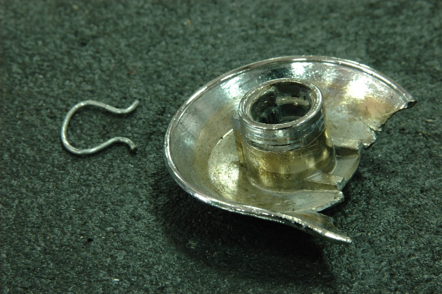
One of the things that pushed us to move away from manual windows: we got tired of the crank handles breaking. This is the third one we went through. Note the clip that holds the handle in place on its splined shaft.
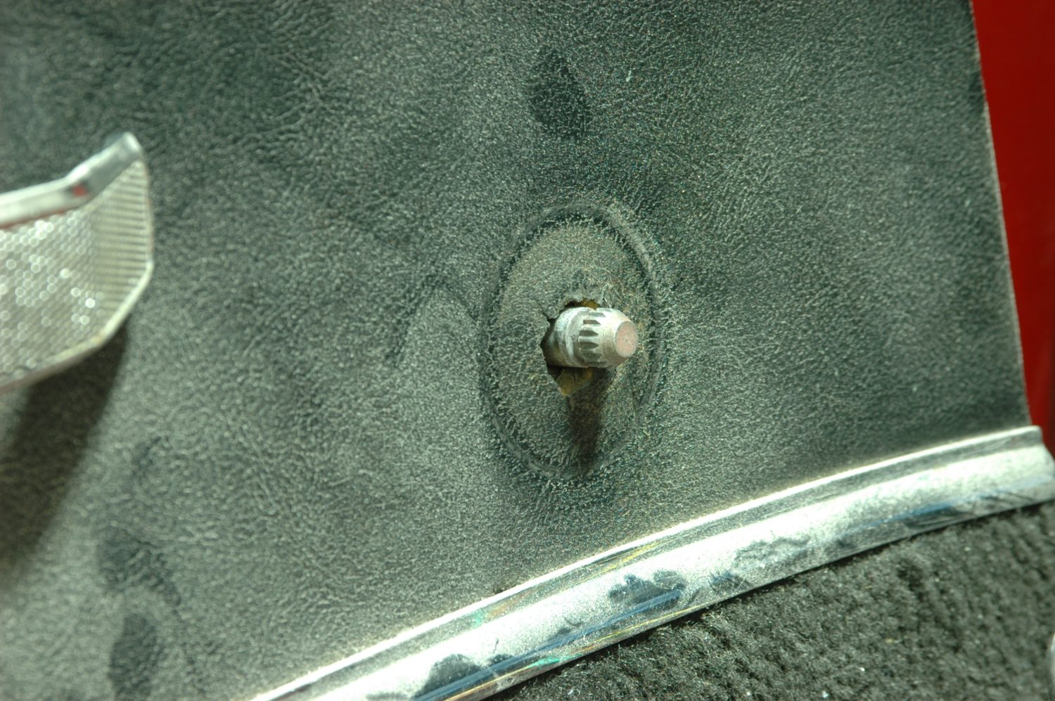
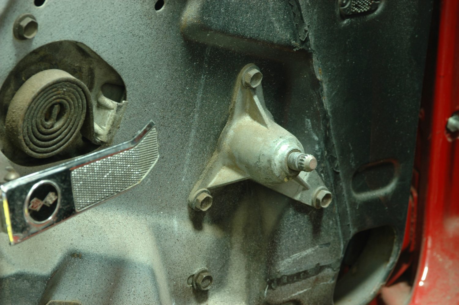
The window crank shaft with the handle removed. The good part about this job is how much access you have to the knob to insert a tool: not so with the lock knob.
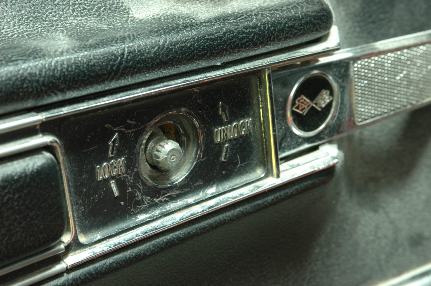
The lock plate with its knob removed. Note how little room the plate gives you to access the knob, and how easy it is to scratch. For this part, you may prefer to use a shop rag to snag the end of the clip and pry it off.

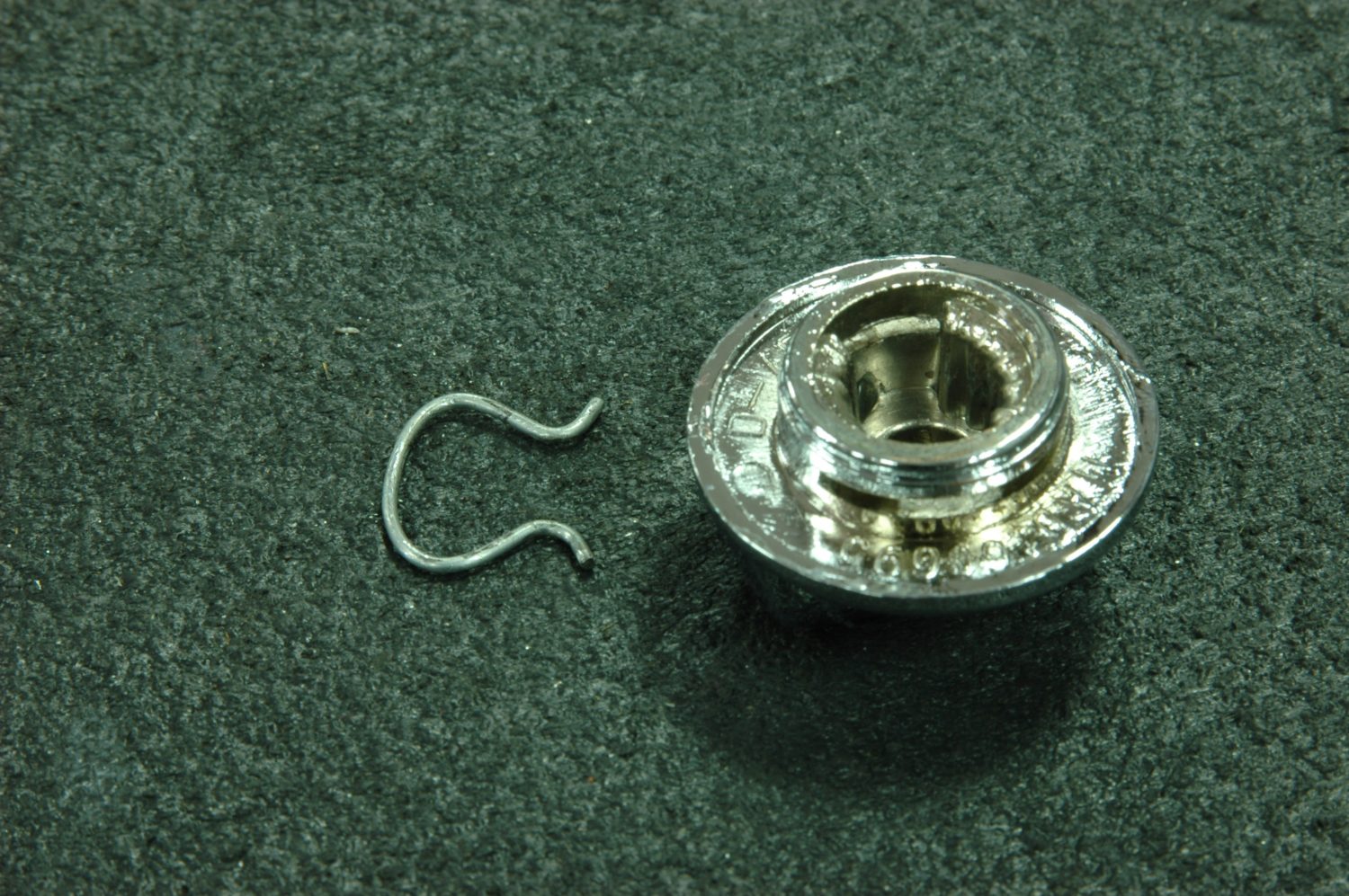
The back of the lock knob, with its locking clip. It installs and removes just like the crank handle, only with a little less room in which to work.
With those off, take out the screws holding the door panel in place, including the ones for the door pull. Before removing the panel, remember to lift it upwards to free the top lip holding it in place. You don’t absolutely have to take off the door handle before removing the panel, but it’s easier if you do. At the bottom of the door is an access panel that will also need to come off, as will the crank mechanism.
The door pull will have to come off for the panel to be removed.
Remove the other mounting screws and lift the panel up (it has a lip at the top) and off the door.
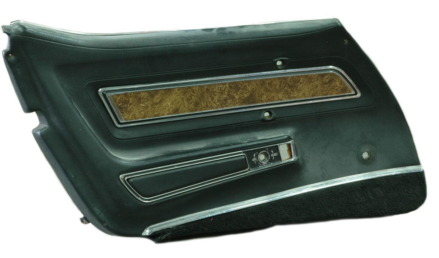
The door panel off the car. Note the hole where the window crank used to be: it will not be used with the electric conversion. While it’s possible to simply plug the hole, we’ll be replacing both it and the more worn passenger’s side panel with a new pair from Corvette Central.
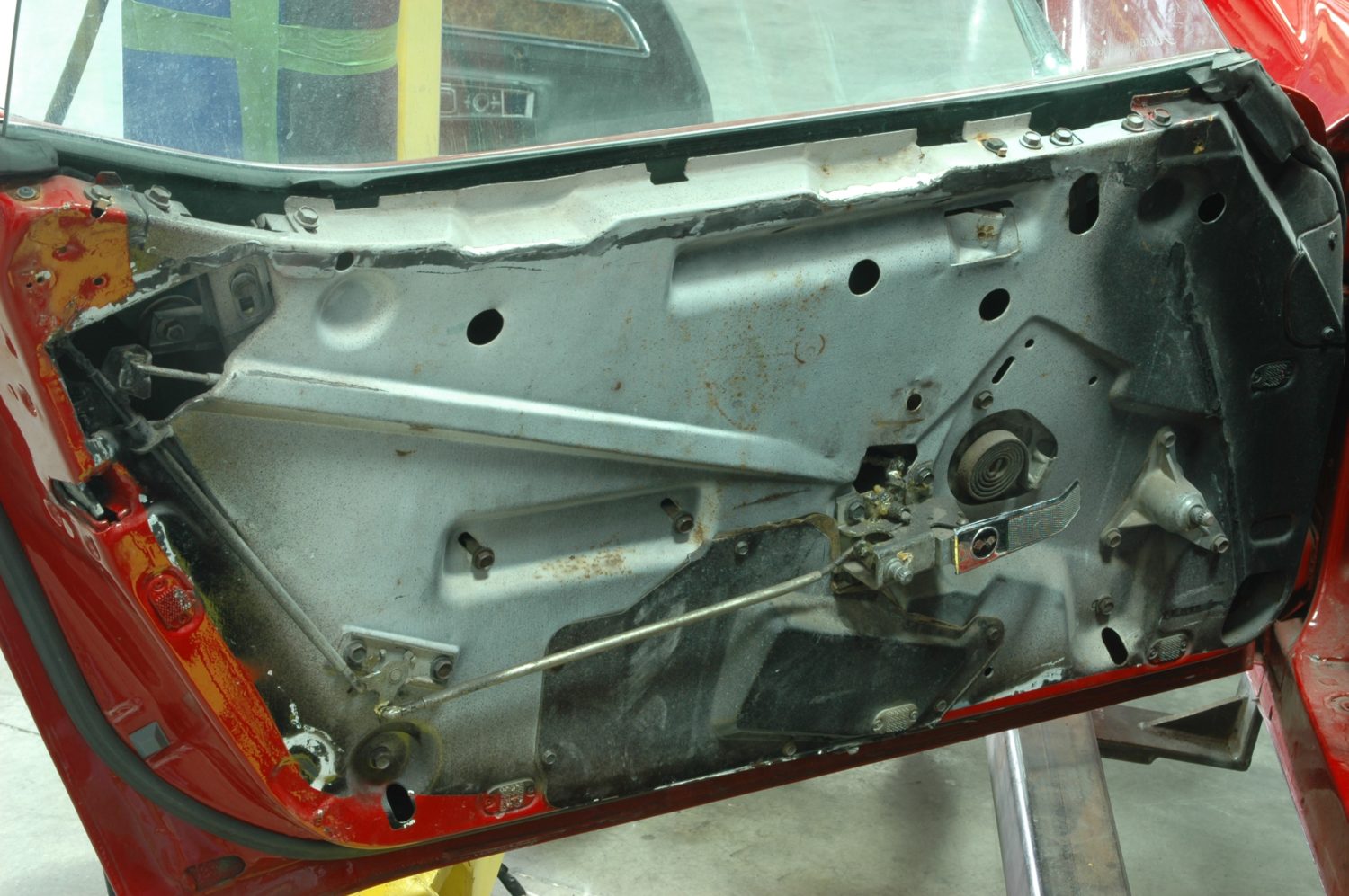
Door with the panel removed. The next order of business is to get access to the window and regulator assembly and remove them.
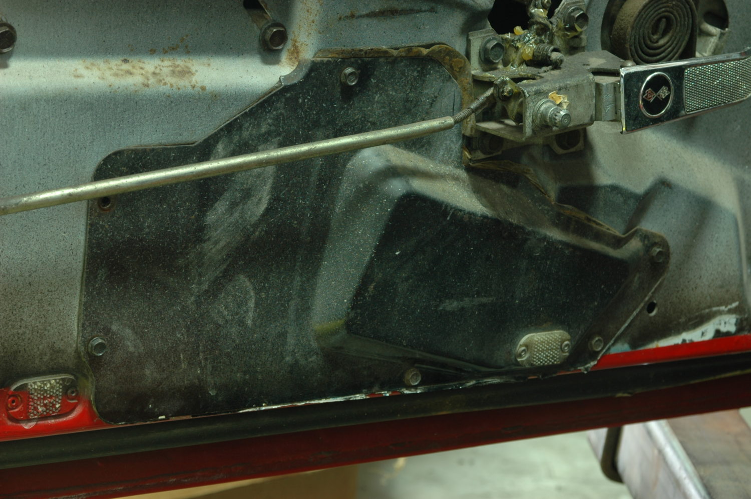
This access panel, which is held on with hex-head screws, has to come off to get access to the inside of the door.
Next out is the side window and regulator that holds it. Think of a pair of scissors held vertically with the handles down—when the blades are spread far apart, they have less “height”. As the handles are squeezed together, the blades get closer and the whole thing gets “taller”. That’s basically how the regulator works: three ends of the regulator’s “x” run in tracks on the door or glass, and the fourth (the lowest one closest to the front of the car) is the “handle”, operated either by motor or hand crank to make the window go up or down.
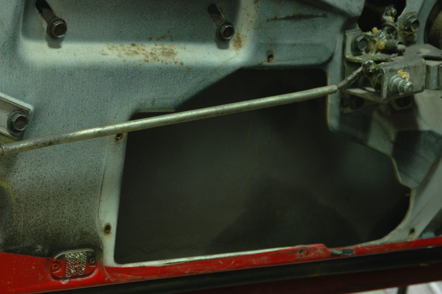
Door with the access panel removed. Once the regulator has been freed from its mounting points inside the door, it will collapse and be removed through here.
We won’t need the manual crank mechanism anymore, so off it comes. This serves to connect the crank handle with the regulator inside the body of the door.
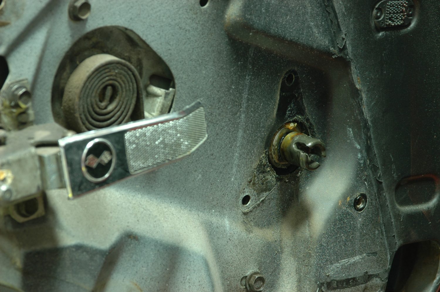
The manual input for the regulator after the crank mechanism has been removed. Also note the door handle is still in place—you can remove the door panel without taking off the handle (we did), but it’s much easier to free the panel if you remove the handle first.

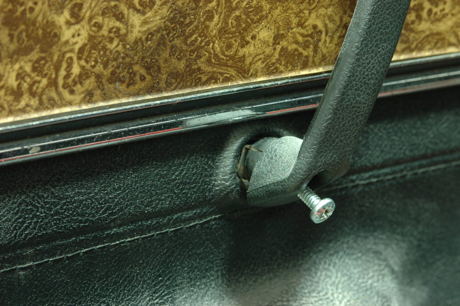
The door handle shown from the rear. The T-shaped part is keyed into the internal mechanism, and then held in place with a screw that goes through the hole. Unscrew it, then slide the handle forward and off.
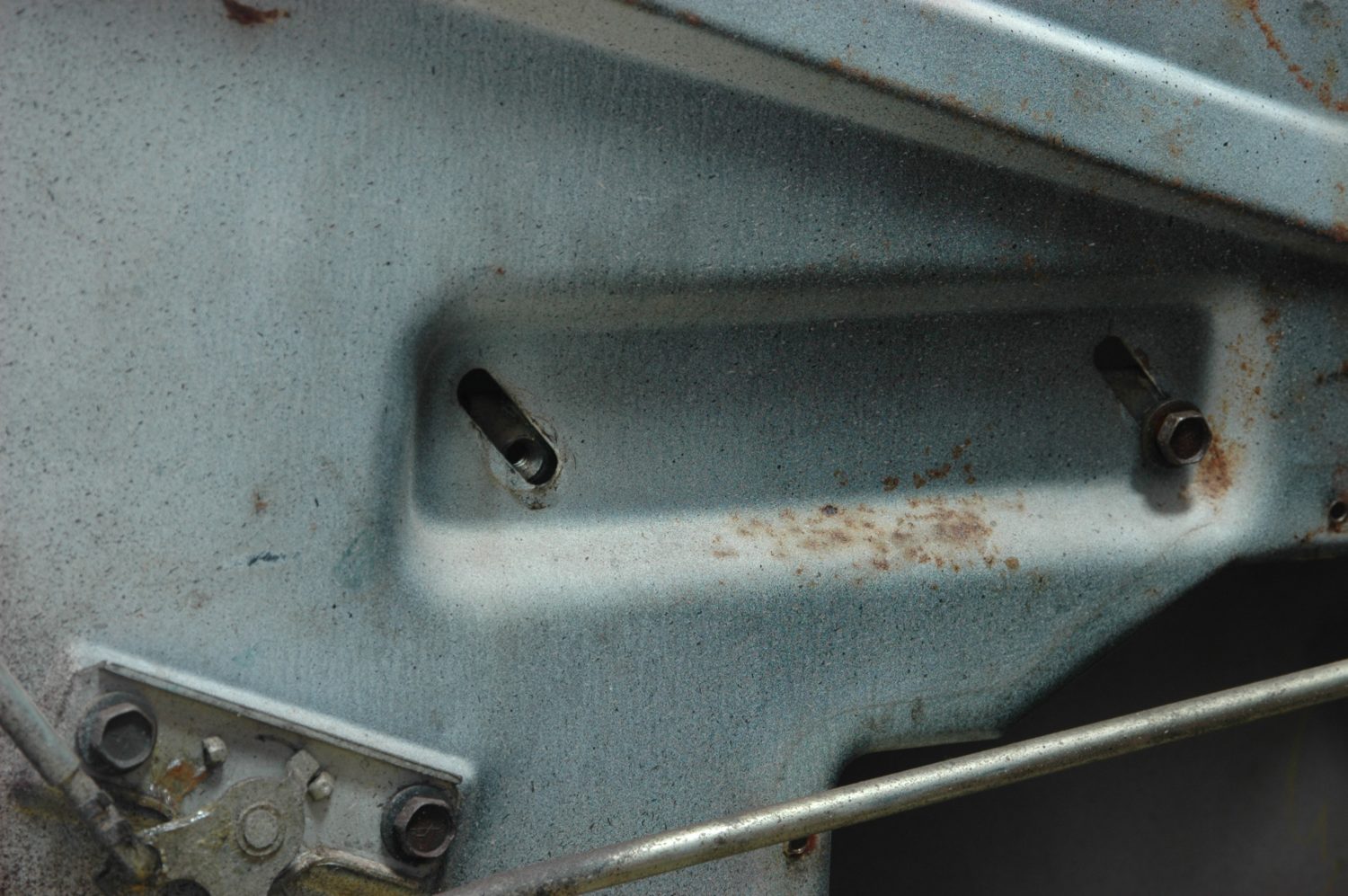
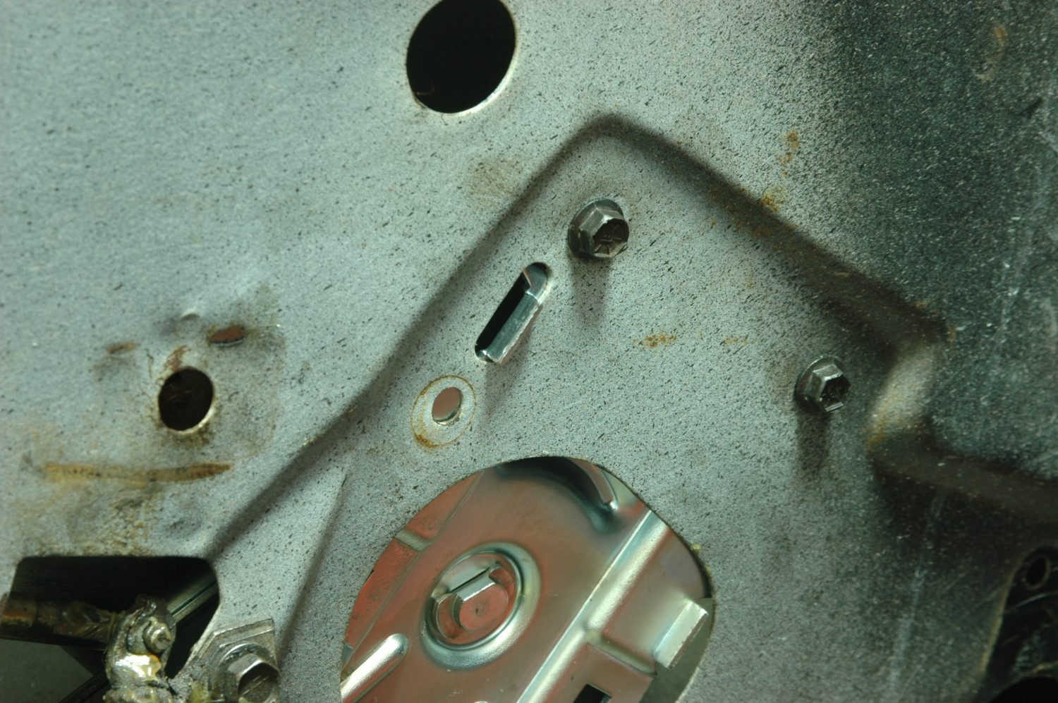
The lower horizontal track in which part of the regulator rides is mounted via these two holes. Note the angled slots, which are used to adjust the window. You’ll need to readjust the window height and angle upon reassembly.
Removing the regulator requires a working knowledge of its mounting points, and while you can learn from trial and error, looking at the assembly manual will help. There are two horizontal tracks (one on the door, one on the glass) the regulator rides in, and two vertical tracks the window rides in. You’ll need to remove all but the track on the window (we removed a roller instead) to free the window from the regulator. Once the door glass is free, carefully remove it. The regulator can then be collapsed and removed from the access hole in the bottom of the door.
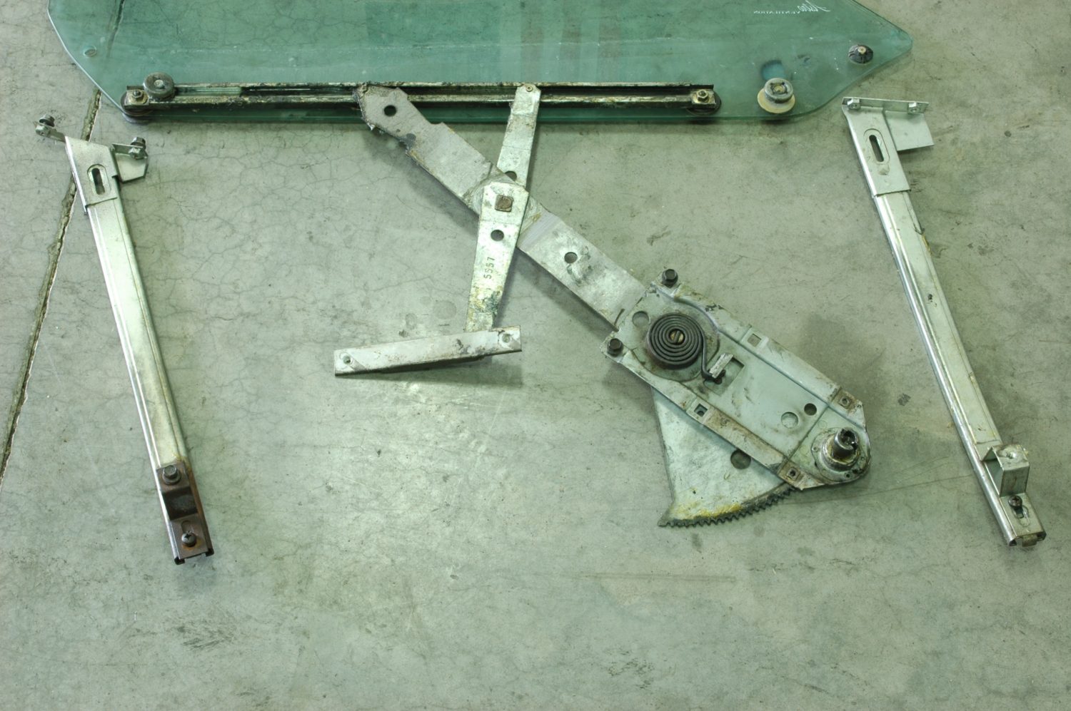
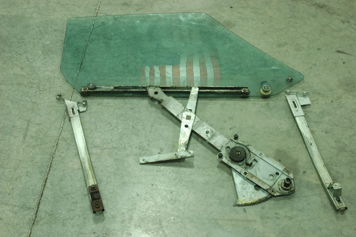
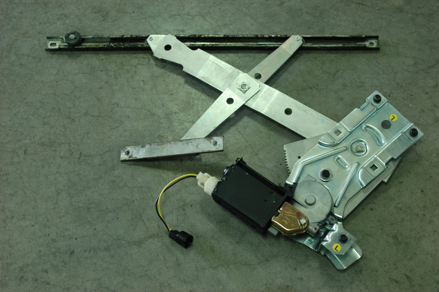
The regulator assembly and window tracks after removal from the car. Note the long horizontal track attached to the window and the shorter track that attaches to the door through the two diagonal slots.
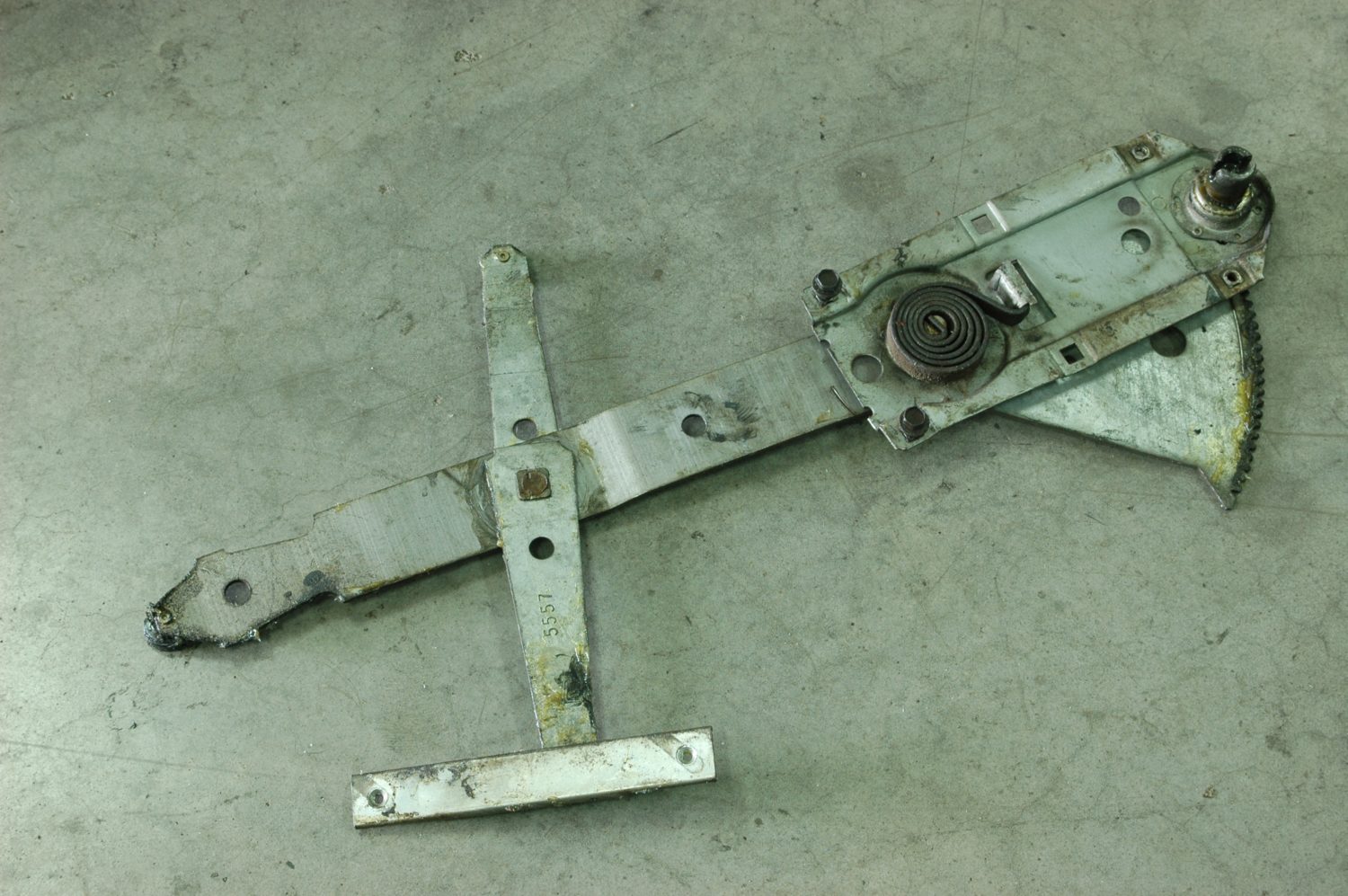
The manual regulator. Think of it as a pair of scissors: the top and left arms ride in the long horizontal track attached the window via rollers (not visible in this photo). The crank mechanism on the right is fixed to the door panel, as is the short horizontal track at the bottom. As the crank is turned, raising the left arm, it brings it closer to the upper arm, like closing a pair of scissors, pushing the window upwards.
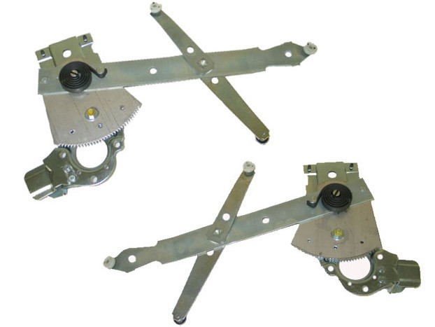
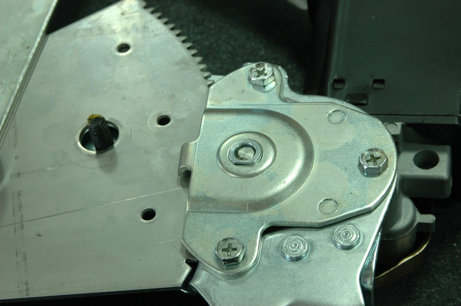
The new window regulators, which works on the same principle. Note the toothed gear is oriented differently to engage with the electric motor. On ours, there was a fine burr on the edge of the teeth, so we hit it on a wire wheel to remove the burr.
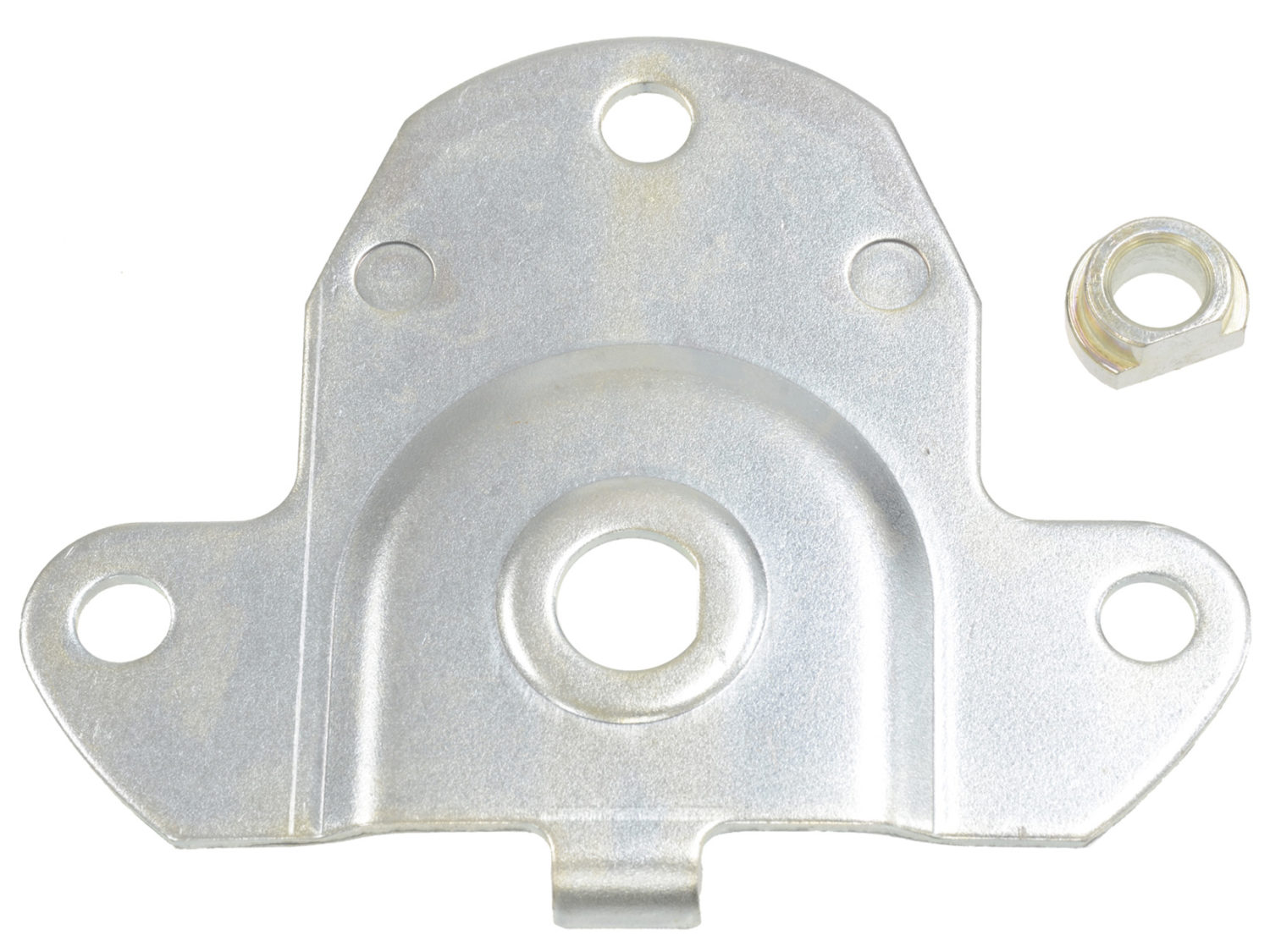
This mounting plate orients the motor and regulator. Note the keyed bushing.
The power window motor mounted in place. This will need to be assembled before installing the regulator in the door, as it points towards the outside of the car. A little grease on the motor output shaft where it passes through the bushing is a good idea.
The power window regulator reinstalls in reverse order, with only a couple of differences. The toothed part of the regulator that mates with the power window motor is spring-loaded and held with a bolt that you’ll want to keep in place as long as possible. When we did this install, we found a fine burr left over from manufacturing on the edges of the teeth, so we removed the bolt and hit the teeth on a wire wheel, which smoothed the burr. We then installed the electric motor to the regulator, slipped the assembly into the door, and bolted it in place as shown in the accompanying photos. That’s pretty much it for the mechanical work.
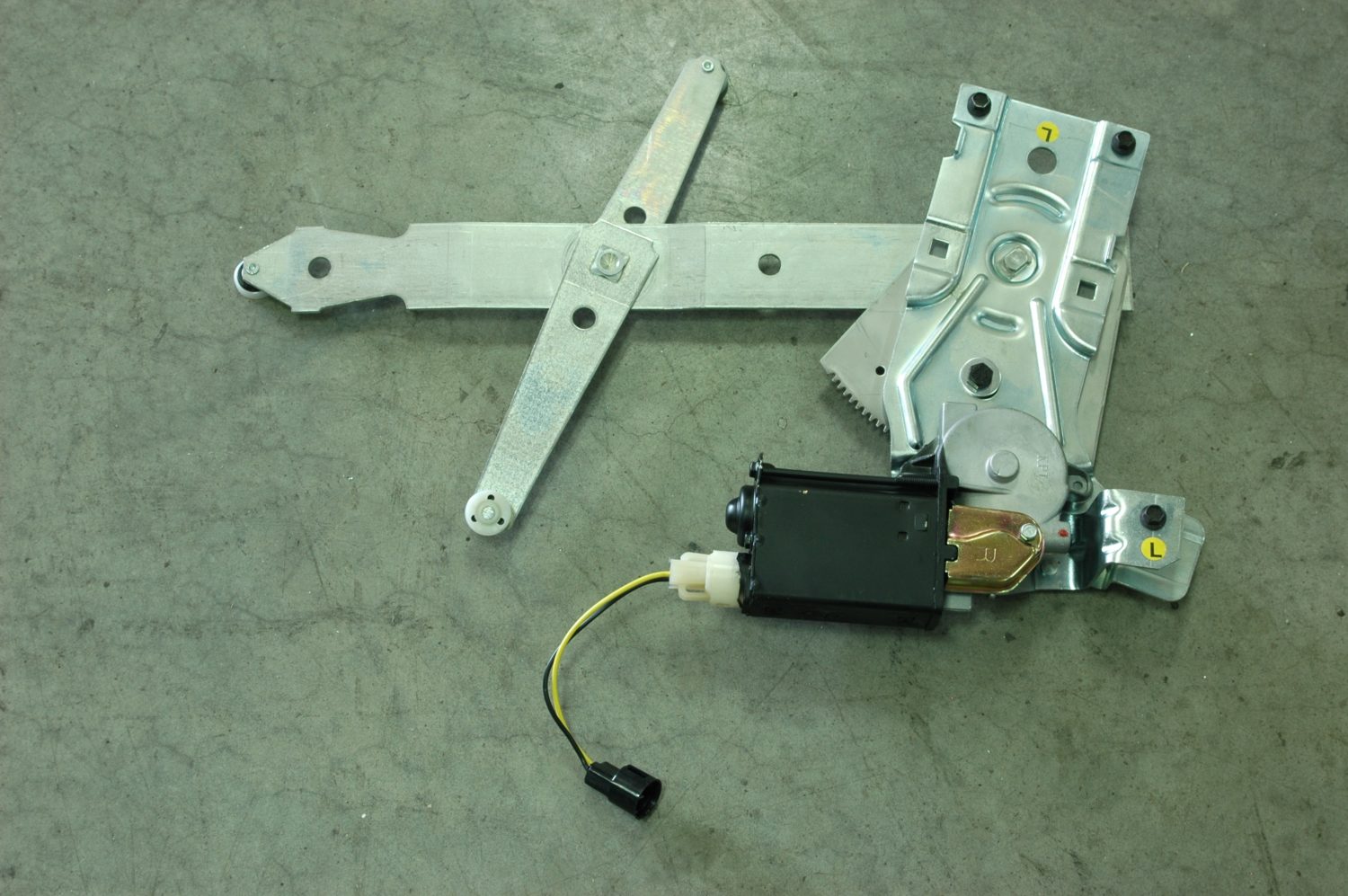
The regulator and motor assembled.
The regulator installed in the two horizontal tracks prior to installation in the door. The top track mounts to the window, the bottom to the door. Note the grease on the track—also not a bad idea.
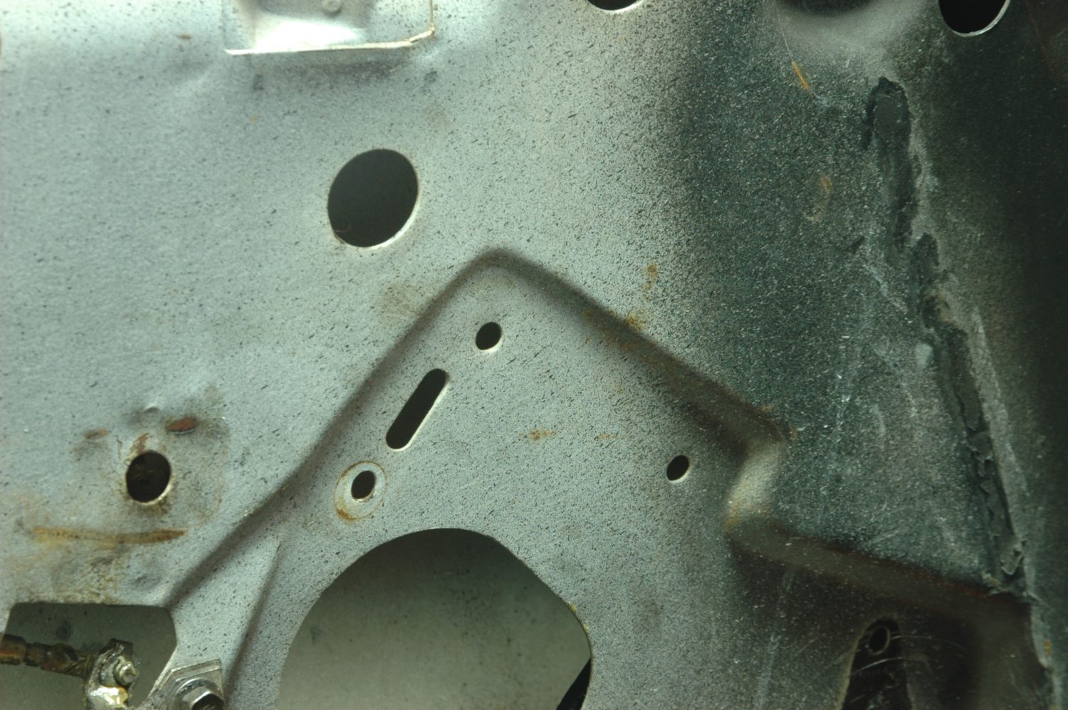
The regulator mounts to the door using two bolts that pass through these holes, and is oriented by a tab that fits into this slot.
The regulator bolted into place.
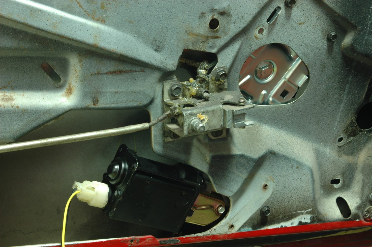
The window regulator and motor in place—notice the additional mounting bolt forward of the motor. Other than covering it all back up, that’s the end of the mechanical part, and it’s time to wire it up.
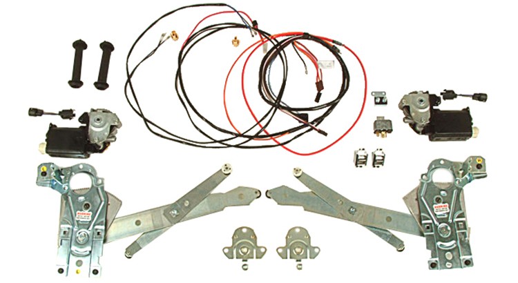
The rest is wiring, which is simple and straight forward since the conversion comes with a plug-and-play harness that requires no modifications to install. Again, it never hurts to read the assembly manual for routing and such things.
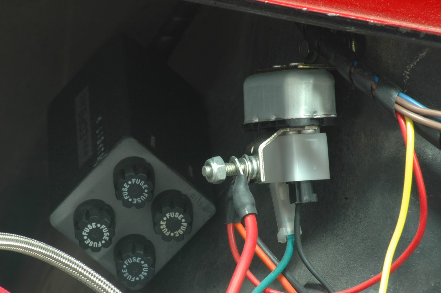
The horn relay, located on the rear of the driver’s side inner fender, serves as a power distribution point for the car. The electric window harness comes with a red heavy gauge power wire terminated with a ring terminal that slips onto the stud and is snugged down with the nut. The fused box behind it is an ECPB electric headlight conversion.
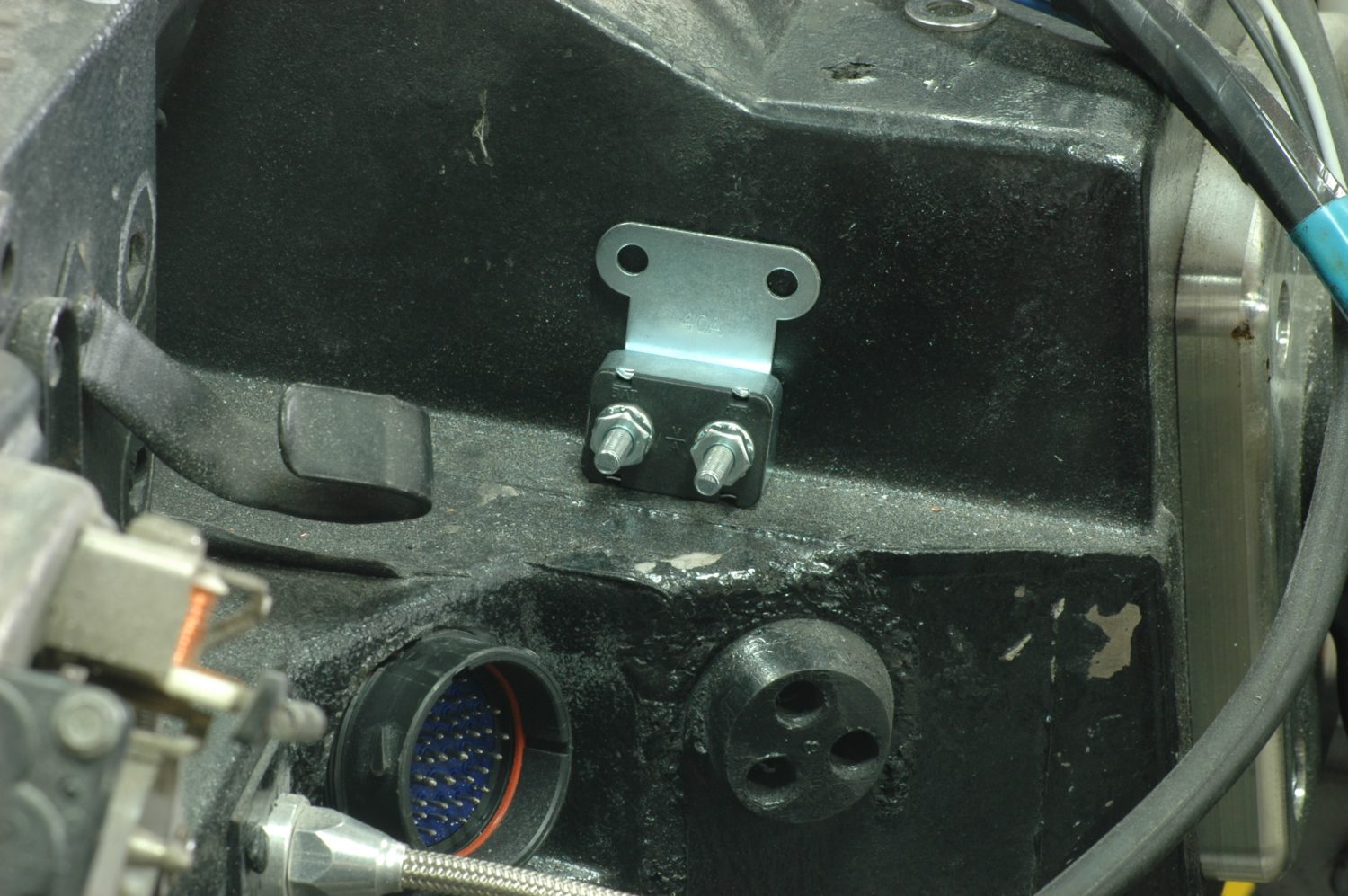
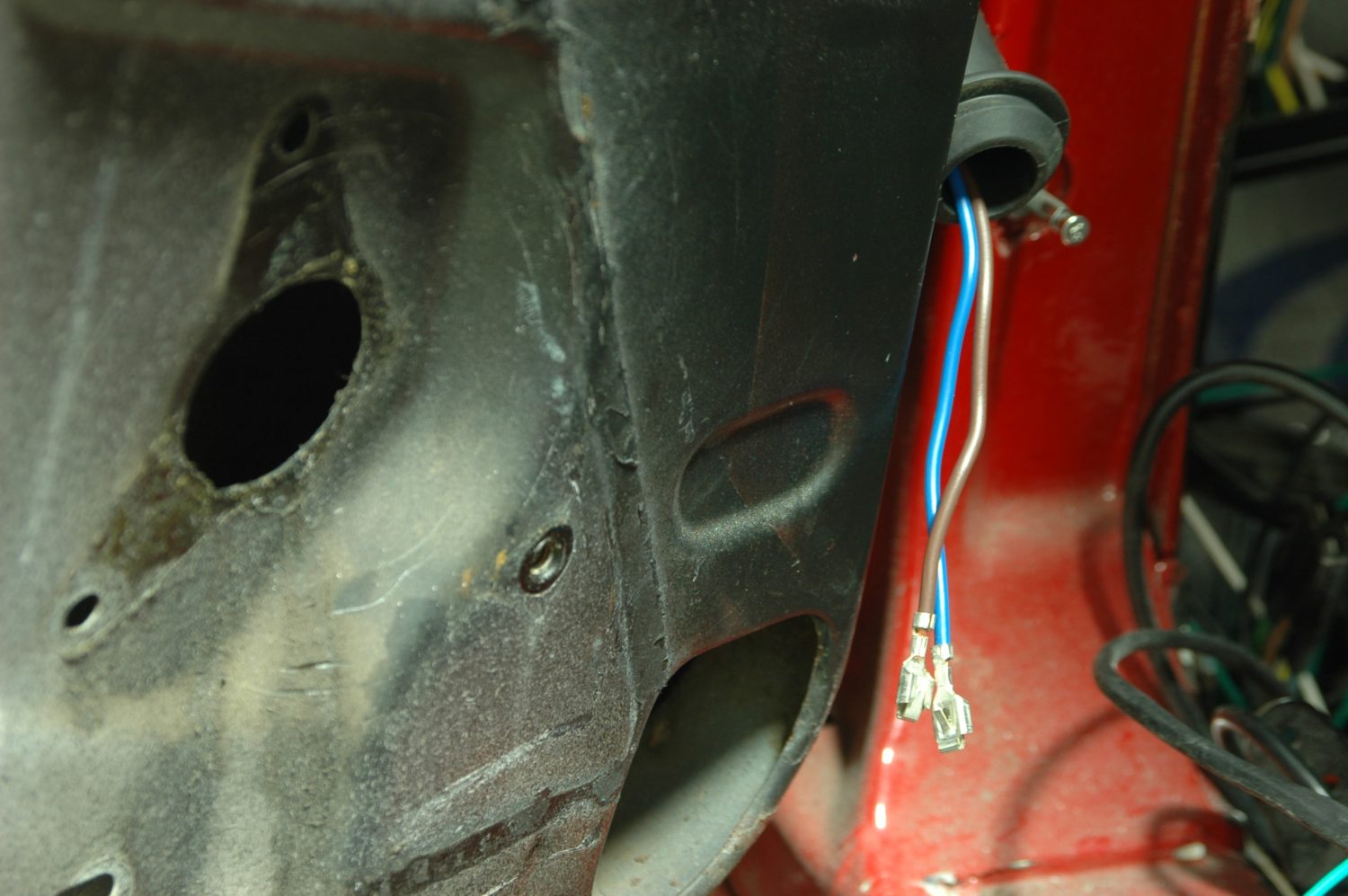
The main power wire goes from the horn relay to this 40 amp circuit breaker, which mounts on this part of the firewall (where varies by year; check your assembly manual). The output wire from the circuit breaker goes through the rubber grommet below it into the car. Alternatively, the more dedicated electrical guys may choose to terminate it with a Packard 56 terminal and route it through the factory bulkhead. The multi-pin connector to the left of the grommet is part of the engine harness for the LS3 installed in this car.
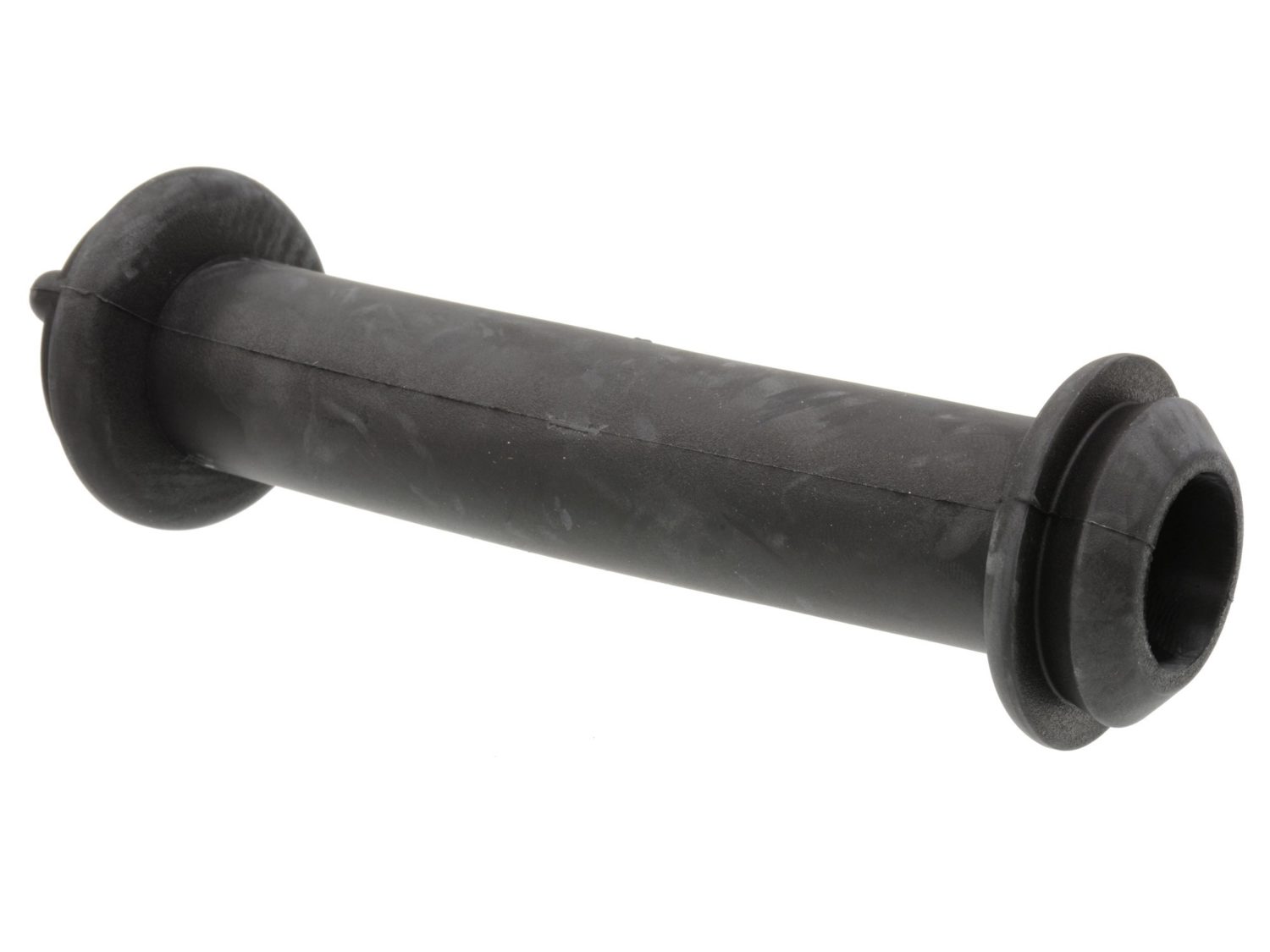
After harness comes into the car via the firewall grommet, it will need to be plugged into the fuseblock in the “IGN FUSED” position, which should be empty. The wiring to each door then passes through this rubber conduit, which will have to be mounted between the door and the jamb.

The two wires to the electric motor are terminated, but will have to be snapped into place in their plastic connector after they’ve been routed through the conduit.

Since electric windows were a factory option, the holes to mount the conduit are already there: you’ll just have to punch out these plugs to expose them.
In the ’72 we’re using for this installation, the horn relay serves as a major power distribution point, and that’s where the wiring starts. Located on the driver’s side inner fender adjacent to the alternator, the relay has a threaded stud to which the red power wire on the conversion is added via a ring terminal. From there, the power goes to a 40 amp circuit breaker that mounts on the firewall (on the passenger’s side protrusion where the brake booster mounts) and a black-striped orange wire takes the power through a rubber grommet into the car. For those who are more electrically inclined and want the cleanest installation possible, it’s also possible to route the power through the factory bulkhead using a 12ga Packard 56 terminal (rated at 49 amps). That’s the route we took, as well as choosing to mount the circuit breaker on the rear of the inner fender next to the horn relay, where it will be out of sight.
The conduit with the inboard side mounted. We went ahead and routed the wires through it before seating the conduit rather than trying to fish them through later.
The installed conduit is barely visible underneath the hinge.

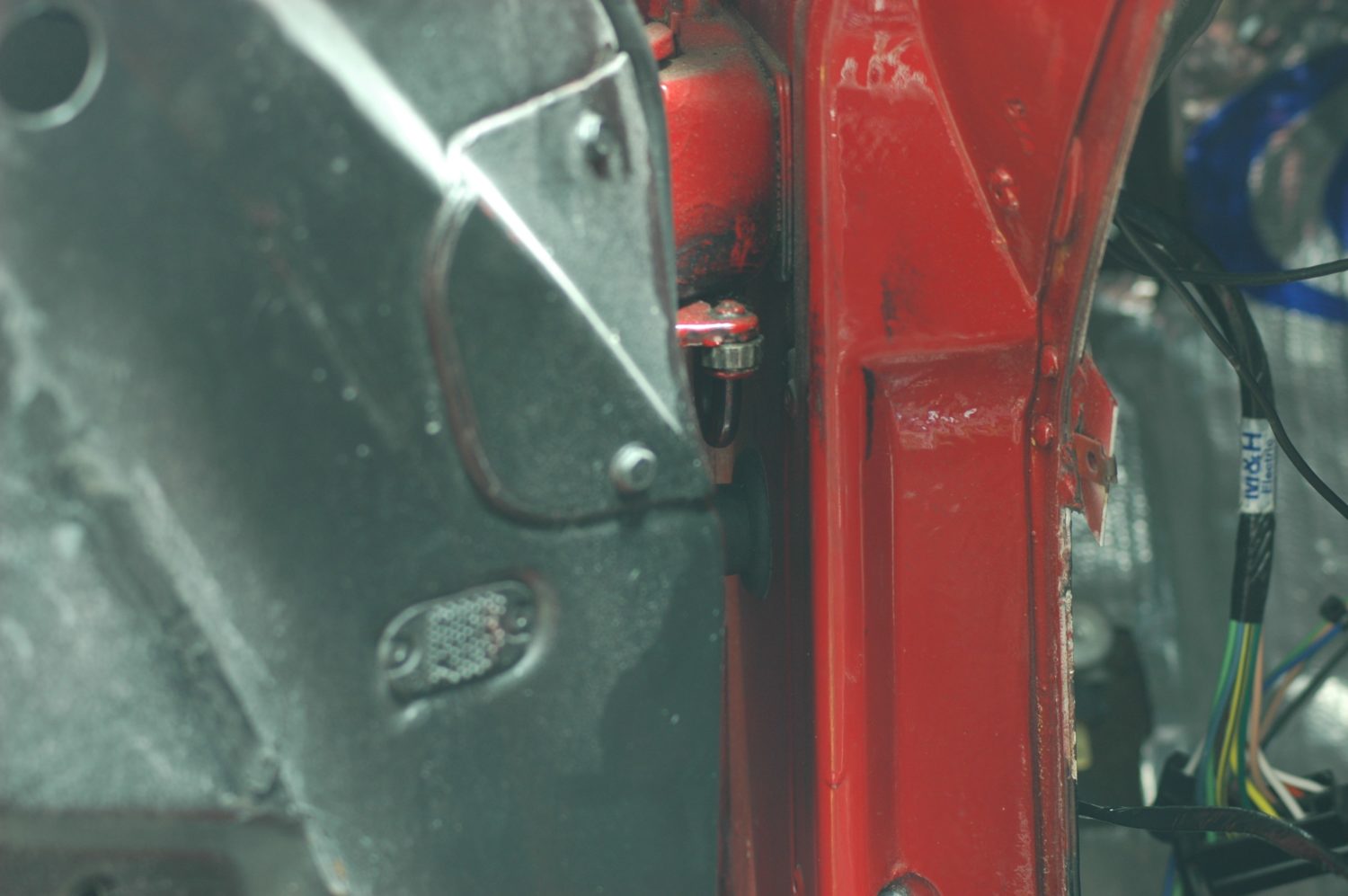
The terminated wires plug into this plastic connector. We used the factory assembly manual to makes sure we had the right wire in the right cavity. It has wire routing as well as orientation of all the regulator components, both of which we found very helpful during this project.
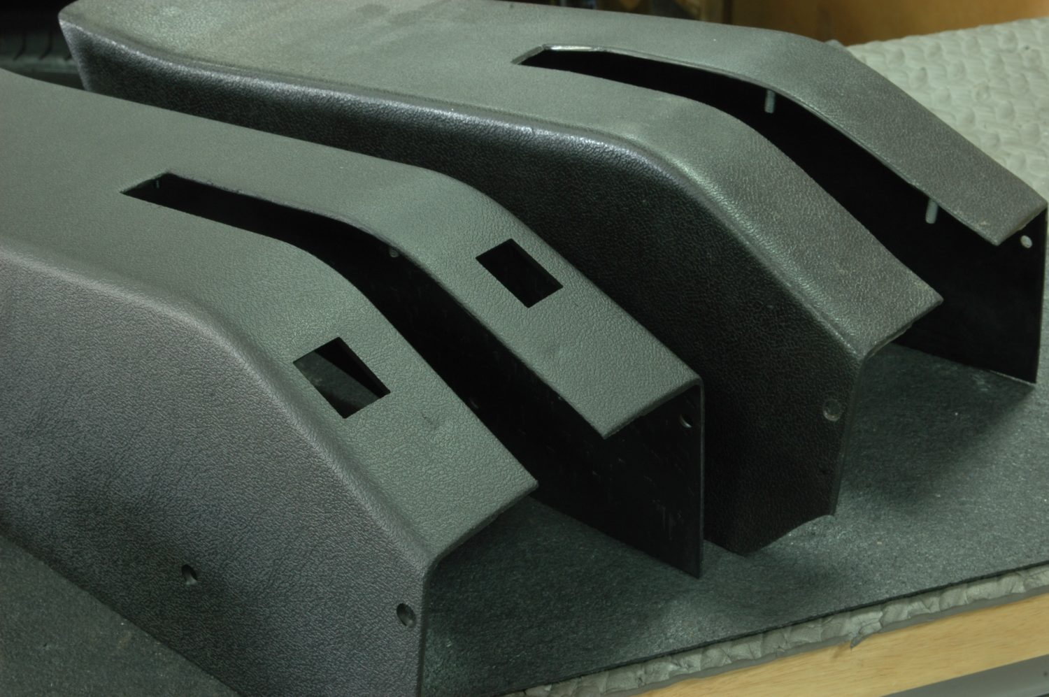
After installing the door wiring, next is mounting the relay and ground wire and then the two switches which go into the parking brake housing. Although we could have modified the one in our car (rear), we ordered a new one from Corvette Central that already had the square holes used to locate the switches.
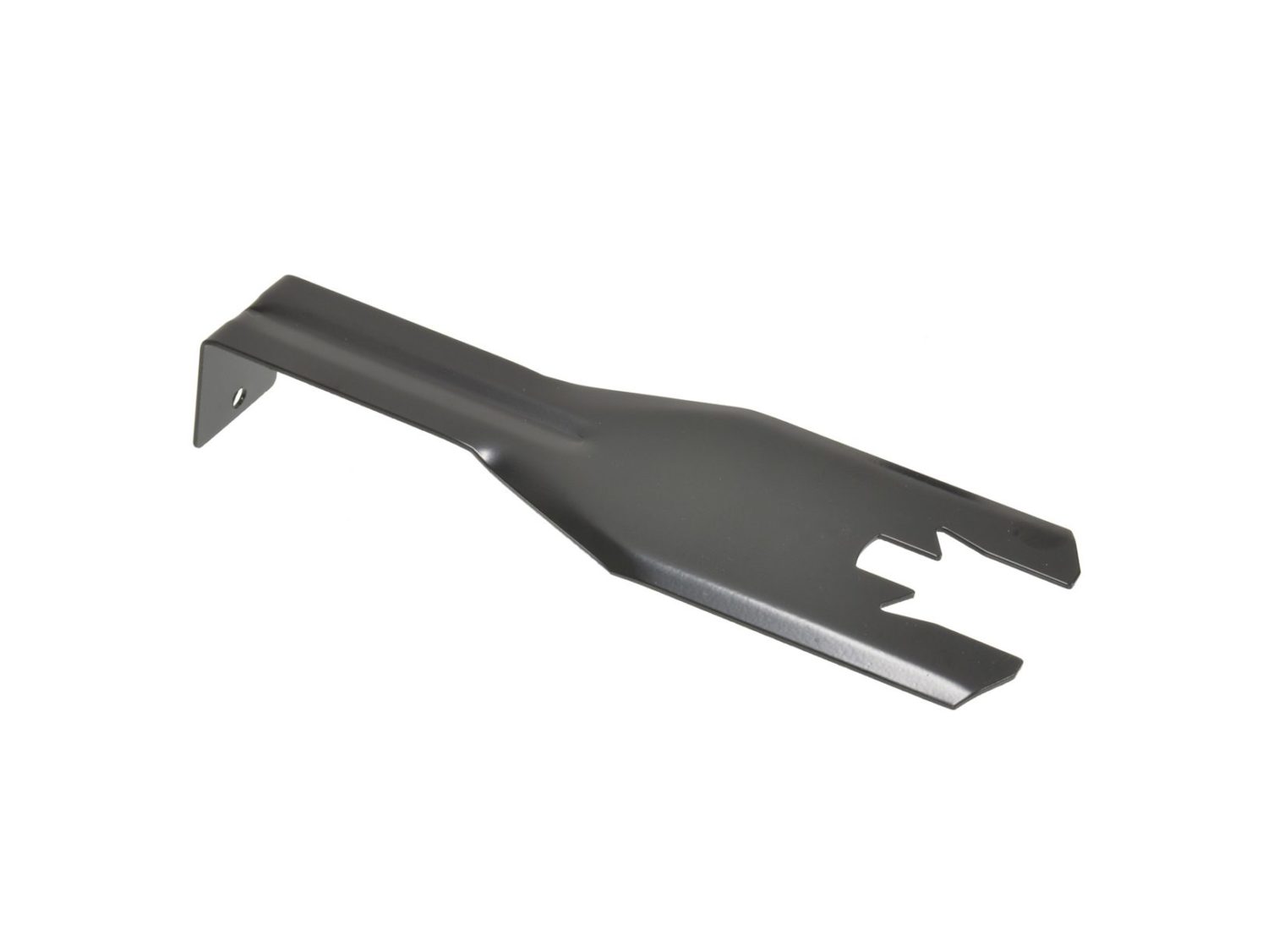
Never put anything back rusty. The support piece for our parking bake housing had seen much better days, so it was time to give it a little attention before putting it in the new parking brake housing.
The interior part of the harness plugs into the fuseblock in the receptacle marked “IGN FUSED” and has an extended plug so that plugging in the harness doesn’t leave you without a source of fused switched power.
The rest of the interior harness includes a metal-bodied relay that mounts (along with the ground wire) under the center console. This leaves us with nothing left but the wires to each door and the switches.
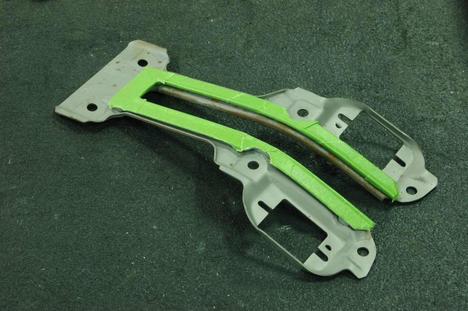
We used painter’s tape to mask off the chrome bits on the support, then bead-blasted it to remove the surface rust. Note that the support already has the mounting holes in place for the window switches.
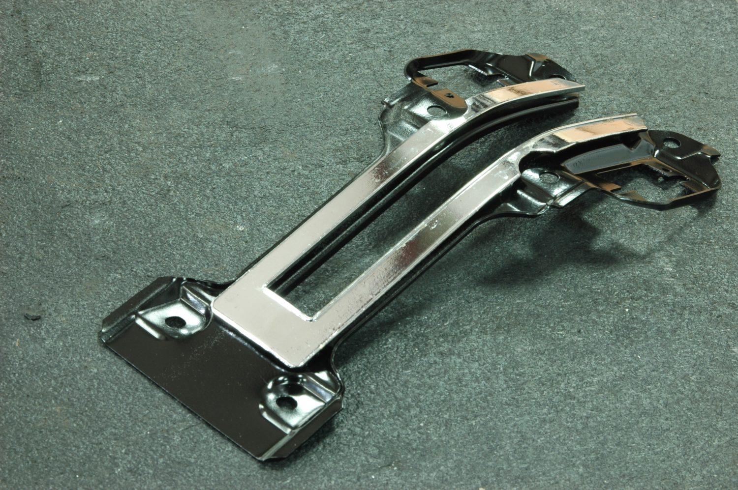
The support after blasting and painting—much better.

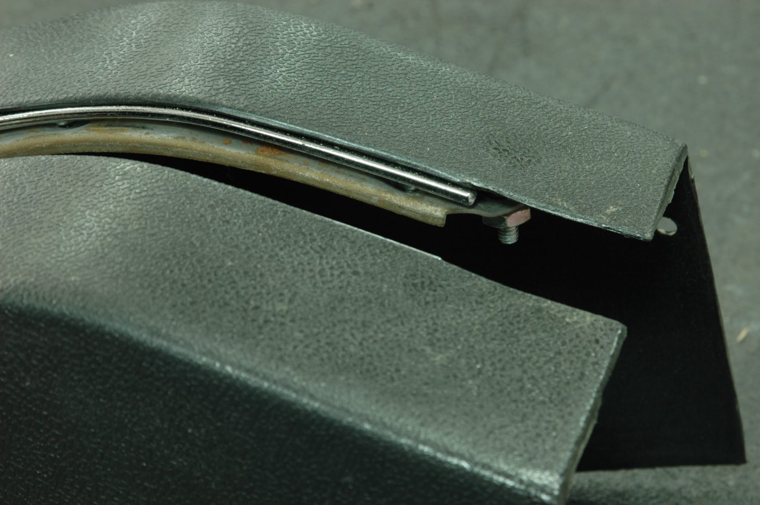
The support mounts to the underside of the housing using these molded-in screws, some of which also serve to connect the housing to the other steel support that holds the housing above the transmission tunnel.
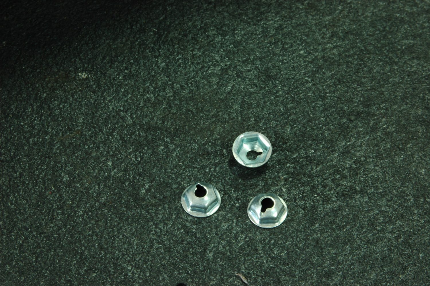
These speed nuts hold the metal support on the parking brake housing. While this may sound obvious, we once spent hours trying to find a conventional nut with the correct thread dimensions.

The support in place in the housing, showing the bracket for the window switches.
The two wires to each door go through a rubber conduit that will squeeze into place between door and jamb, snapping into mounting holes in both places. On cars with original manual windows, expect to find those holes filled with a plug which will push or pry out with a screwdriver. Once the holes are freed up, mount the conduit and route the wires down towards the motor. Now snap the metal terminals on the ends of the wires into place in their plastic connector (consult the assembly manual for correct color coding), and plug it into the motor. That’s it for the work on the doors.

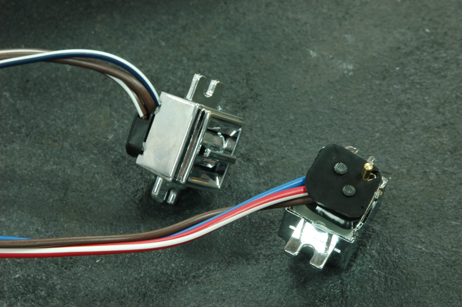
The window switch. Both are identical, and both can only mount one way in the bracket.
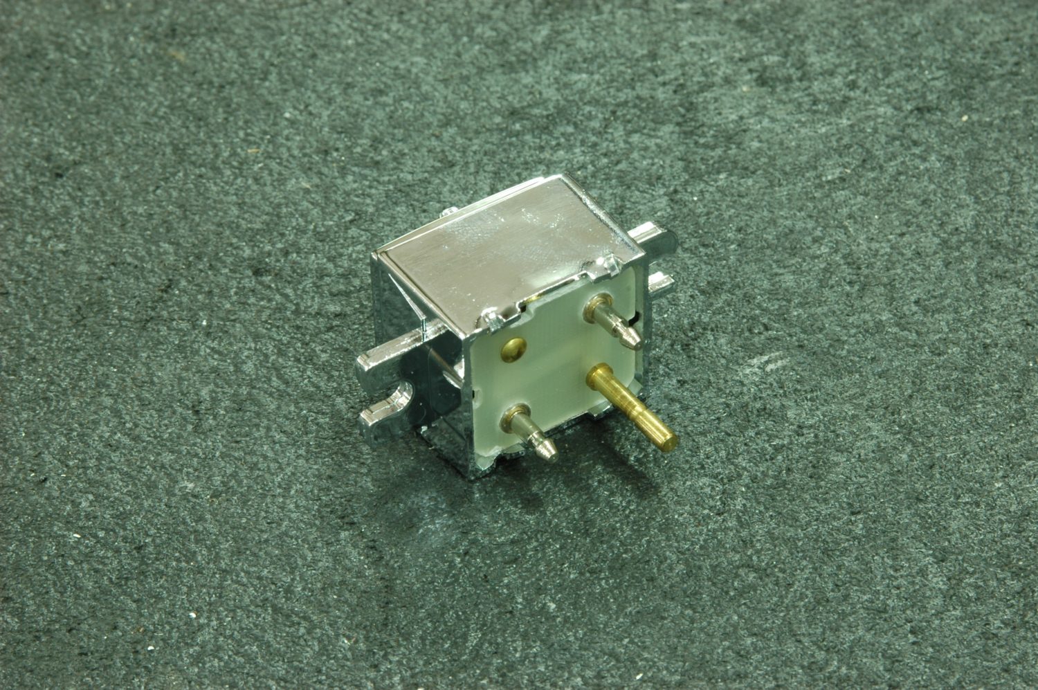
Rear of the window switch. Like their mounting on the support, the wiring only installs one way.
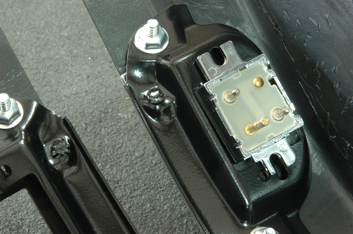
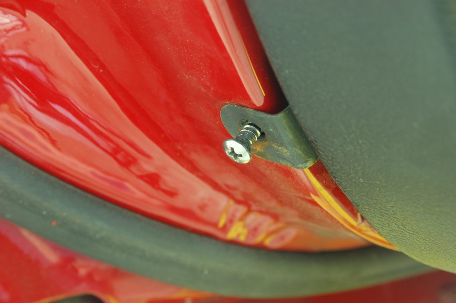
The switch in place on the housing support. It’s held in place with a screw on either end.
The switch end of the wiring harness. The long stud on the back of the switch goes through the middle connection.
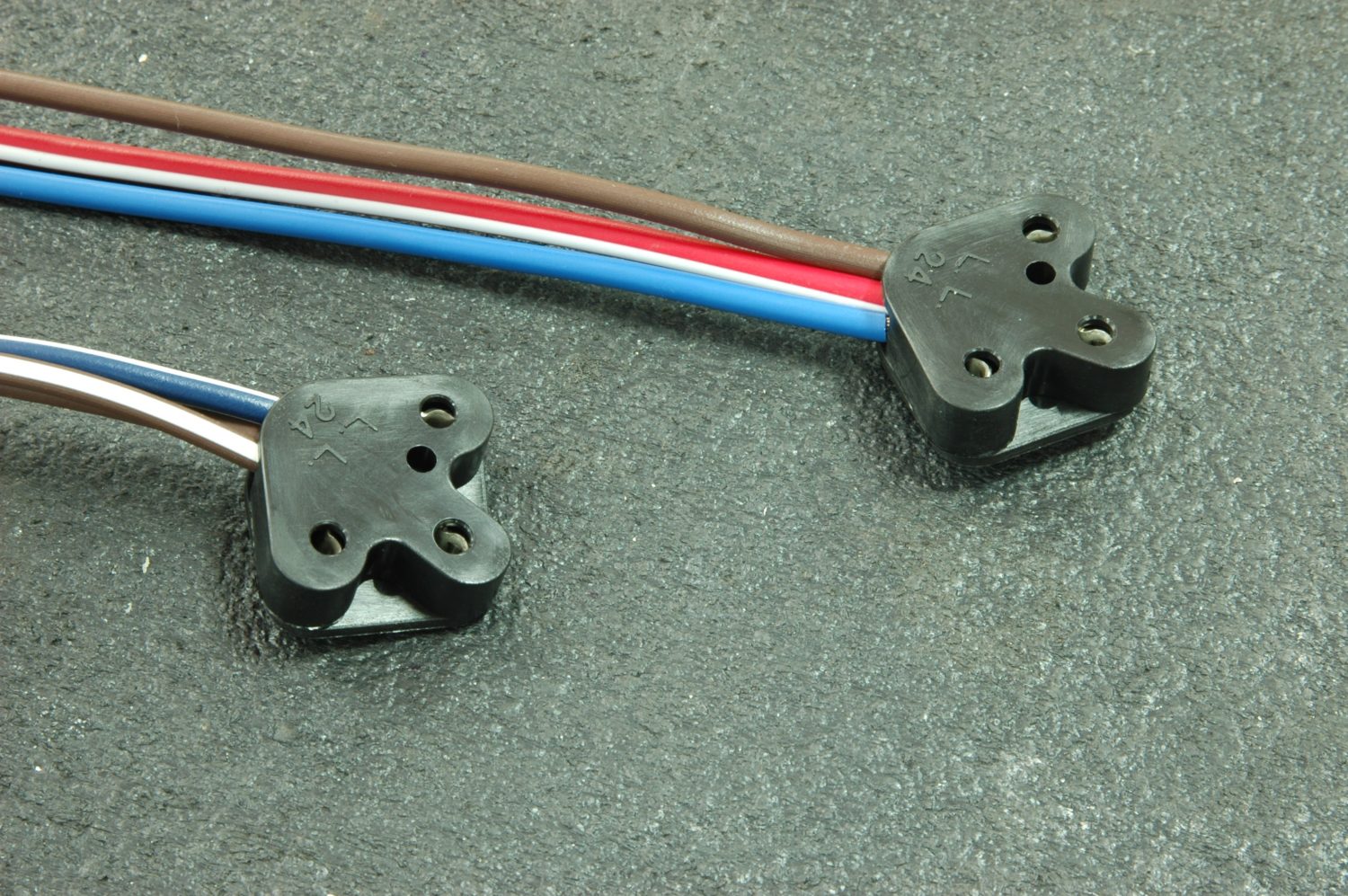
Harness plugged into the power window switches.
To wire the switches…plug them in. The switches mount by screwing into the metal reinforcement of the parking brake housing (the assembly manual calls this a “retainer”) and you’ll find they can only mount one way. Whether or not the car came with electric windows, the metal reinforcing piece should have the mounting brackets already. The factory parking brake housing can be modified for the switches by cutting a rectangular hole to fit the switches, but since our housing had seen much better days, we ordered a correct new one with the holes already in place.

Switch in place and plugged into the harness. The assembly manual suggests the harness is not intended to be removed from the switches if the housing has to be removed.
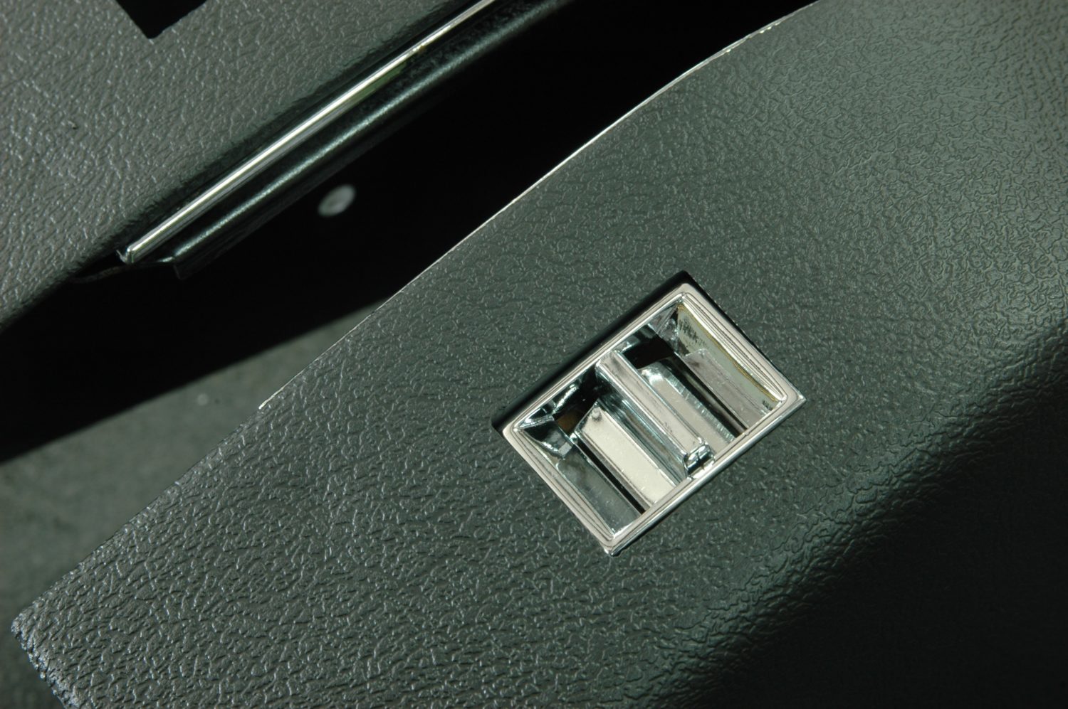
Assembled switch shown from the top of the housing, looking like it grew there.
That’s it—crank it up and go for a ride, and enjoy being able to roll down the passenger’s side window without help.
Resources:
- 1968 Power Window Conversion Kit
- 1969 Power Window Conversion Kit
- 1970-1971 Power Window Conversion Kit
- 1972-1974 Power Window Conversion Kit
- 1975 Power Window Conversion Kit
- Early 1976 Power Window Conversion Kit
- Late 1976 Power Window Conversion Kit
story and photos courtesy Jeremy D. Clough
I’m wondering has anyone selling window motors ever taken one apart to compare it to an original window motor?? I bought 4 motors diff vendors and since one arrived broken mount. I tore it apart and wow not even close to oringnal motor. Ended up new brushes and cleaned throughly and put print. Back in. Money lost but lesson learned!!!!!
Nice work i love reading through
Nice work and i really like all the info i got here
When will you start to stock a drivers manual window regulator for a c3 ? It is strange you don’t, as they do wear out…chris.
Unfortunately, we are not aware of anyone reproducing the manual regulators new at this time, and we do not have anything in the pipeline to have these done. It will be very expensive to tool up for, making the parts themselves very expensive.
when the motor is attached to the spring loaded regulator which is held in place by a bolt (which you recommend to leave in place as long as possible) that will put the motor about 1/3 of the way up/down the tooth end of regulator. will this affect the operation of the window if the motor is 1/3 the way up/down the tooth end of the regulator? I would think one would want the motor either on the end of the teeth or in the middle of the teeth. before i proceed any further i will need to know the answer to this question.
No, this will not affect the operation.
Will this Power window conversion work on a 1975 Corvette with Automatic?
Yes, kit 283196 will work properly for the 1975.
I am working on a 1969 vette with one of your 69 POWER WINDOW CONVERSION kits. I am looking for the wiring diagram. Is there a download somewhere or can i get it emailed to me?
Thank you.
I’m not aware of a download for this. This is something you would normally find in the GM assembly manual (113076), which you should definitely have if you are doing an upgrade such as this. It shows all of the exploded views of how the car was assembled at the factory, as well as an option section that includes power window views. If you want to e-mail us at mail@corvettecentral.com , we can try to send you a scanned page to view from the wiring diagram.
Will a 91 dash fit in a 86?
No, The 86-89 would be the same, but in 1990 the dash pad completely changed and will not fit the earlier C4’s.
I would like to go from an electric to manual. I have a 1982. Can this be done? Is there a kit for that?
Unfortunately, there are no manual window regulators being reproduced at this time so we do not have the parts required for this conversion.
What is the correct kit for a 1979?
I want to change to manual windows. What is involved and the parts I will need?
Could you please list all tools that are necessary for window and door removal? It makes it much easier for us seniors to sit down with all necessary tools and not have to get up and down.
Unfortunately we didn’t keep track of tools needed when we did this install. We will keep that in mind though when doing future install articles.