This is the second installment of a C4 suspension overview series. Click to view the first article, Click to view the third article.
Once all the original bushings are pushed out and the parts cleaned up bushing installation can begin.
There are a couple of things to be aware of before the first bushing is installed. The bushing bore must be clean and free of any snags of metal that may have been raised during the bushing removal process. Powder-coat or paint may also be in the bushing bore and should be removed to ease bushing installation. A raised area, whether it be paint, powder-coat or gnarled metal, causes the bushings inner sleeve to drag on the urethane, preventing smooth suspension movement. Unlike rubber bushings, urethane bushings should rotate smoothly throughout their suspension range of motion (one of the major reasons for the change to urethane). Too much clean-up of the bores is also a concern: the bushing should require effort to push in. You should be able to squeeze your hand and force the bushings in.
The bushing sleeves take some force to push in. It usually takes a vise or a large pair of pliers to aid in the sleeve installation.
These lower control arm bushings from a Corvette Central urethane bushing kit are being pushed in not quite as easily as this photo shows. I usually start the bushing in the control arm with the arm end sitting on the work bench, then the bushing is pushed into the bore. Note there is no lubricant silicone on the bushings. They should not rotate in the control arm bore. The outer raised edge of the bushing must sit flat against the control arm end. If not, you will have a difficult time getting the arm end to go into the chassis mounting point.
Now the bushing’s sleeve area should be lubricated with the supplied silicone grease. It’s a good idea to wipe the lube inside both bushings.
The sleeve also should be lubricated with the supplied grease, coating the entire exterior of the sleeve.
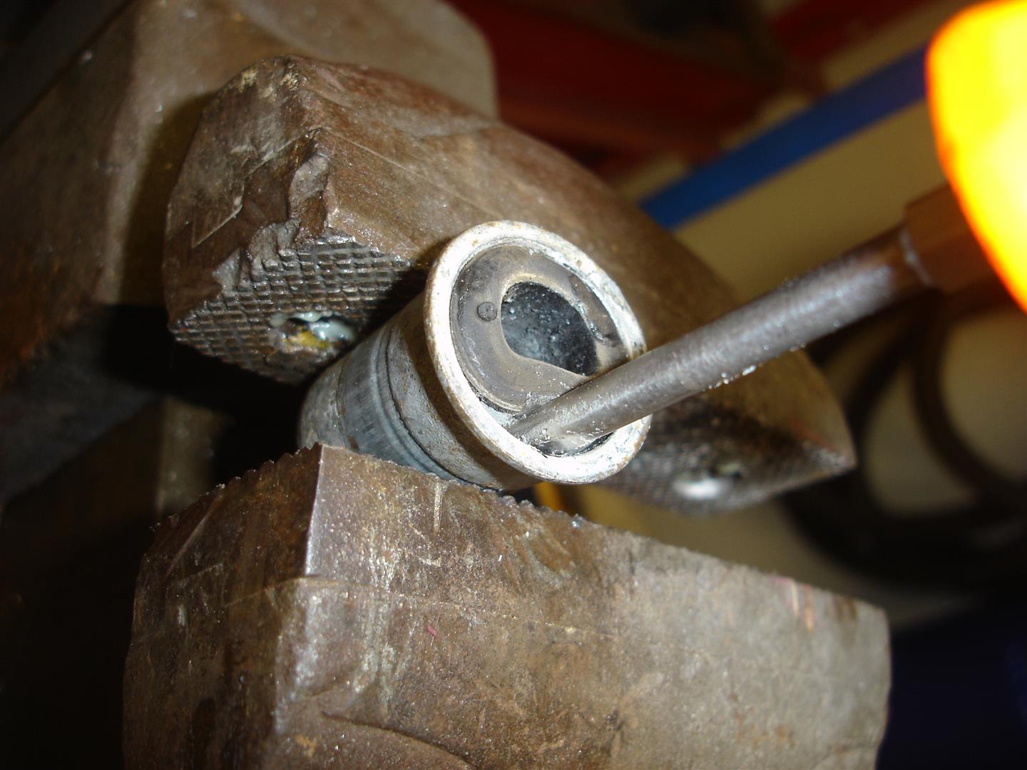
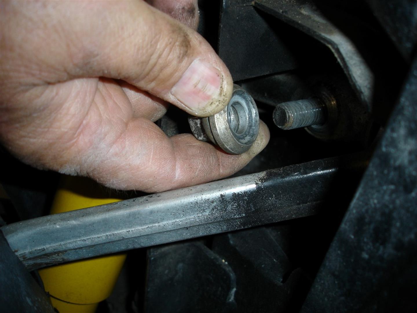
This is one way to push the sleeve in place. Note the grease building up as the sleeve is pushed into the bushing. The sleeve may seem to be tighter in the bushing than the bushing was in the bore; it is not though, the sleeve has to be pushed into the two separate bushings. Once the sleeve passes through both bushings, they become aligned and the sleeve should rotate without moving the bushings in the bushing bore. If the bushings and sleeve rotate together, the bore is too large or the sleeves outer diameter is too large. In some cases a piece of Scotch-Brite can be used to polish up the sleeve to remove any burrs that may be causing the extra tight sleeve fit. Remember: the sleeve should be tight, although it should rotate without extreme effort for the best suspension flexibility during road anomalies.
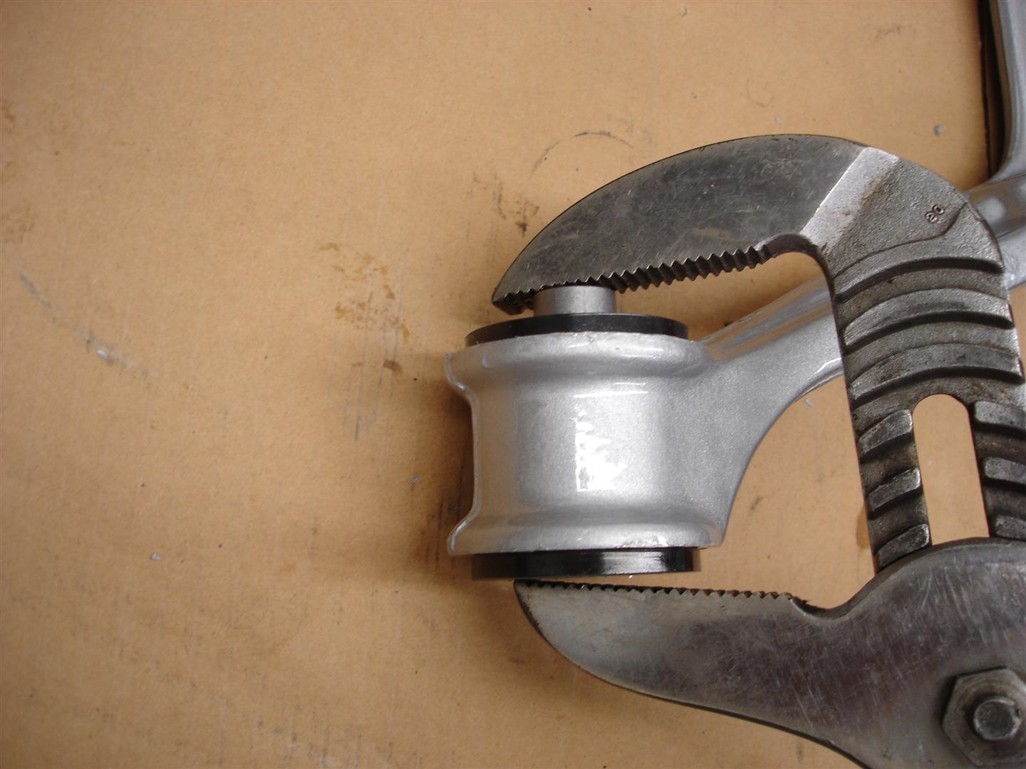
This large pair of Channel-lock pliers will suffice for sleeve installation. If I were using them, I would have put a piece of wood like a paint stick on the bushing side to keep from marking the urethane bushing during the big squeeze. I also put the pivot bolt through the sleeve to make sure there are no raised ridges causing the bolt to stick as it is pushed through. If the sleeve has any obstructions causing the bolt to be tight or not push through easily, use a rat-tail file to smooth the inner sleeve bore area.

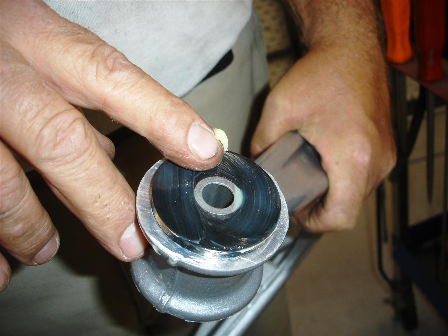
Ball joint installation is next; here I am using a sanding roll on a high speed grinder to remove any paint or nicks that might be in the bore. Use caution here: do not remove any control arm material; only paint, powder-coat or debris. The ball joint relies on a press-fit and it must be tight once installed.
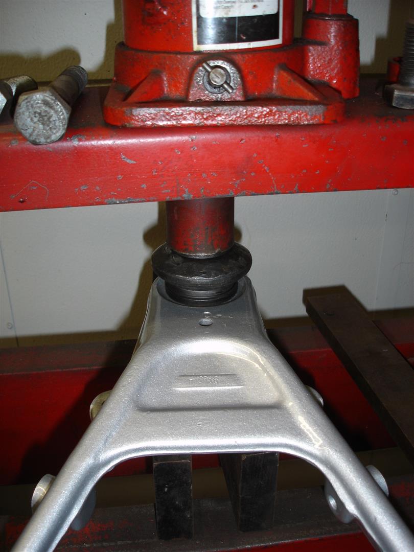
I prefer to use a hydraulic press for ball joint installation. It’s much easier to square up the ball joint during the big push. On the bottom side, a receiver sleeve bigger than the ball joint itself is used and then a disc sits on top of the ball joint during installation. You need to watch that the ball joint goes in straight, if it goes off to one side stop and push the ball joint out and try again.
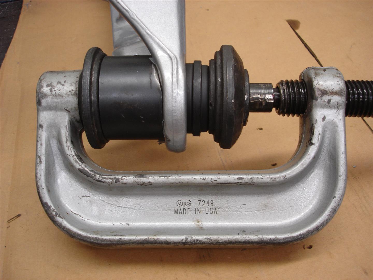
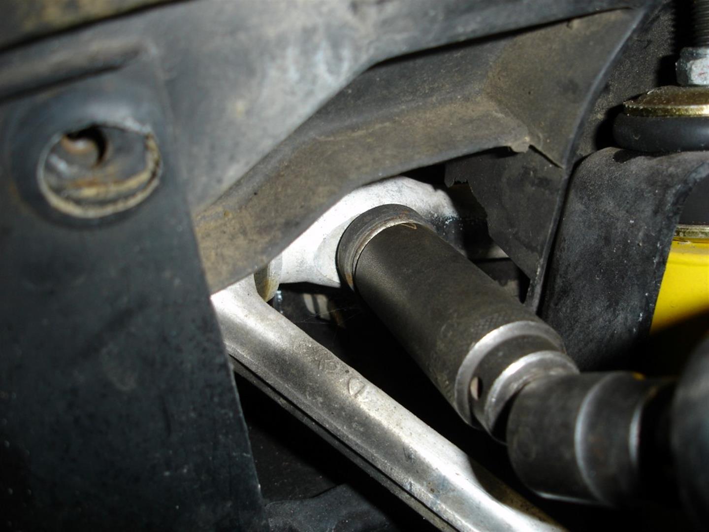
This OTC ball joint press works well for installing the ball joints when the control arm is on the car. You do have to be careful: if you look closely, the ball joint is off to one side as it is being pushed in. This is not good, as it goes in at an angle it tears material away from the bore and it may seem tight but it really is not. If the ball joint goes off too far off center, it can break the control arm. Patience is the key. Monitor the ball joint as it is installed and take action if it is not going in square.
The same procedure is used for the upper control arm urethane bushing install. Start by installing one set of bushings in one end. Avoid putting any stress on the control arms two strut pieces, as they can be bent or worse yet broken. Remember: no grease on the bushing as it goes into the control arm end.
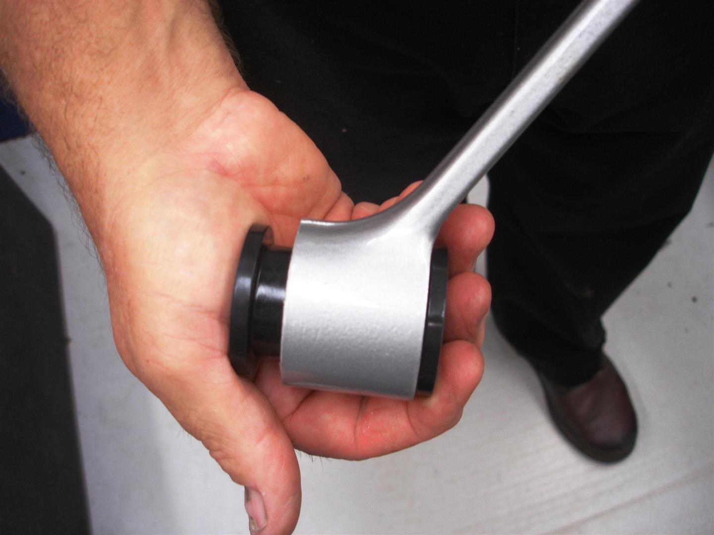
I have found that the sleeves go into the bushings slightly easier on the upper control arms. On its side they can be pushed in this manner. Note the silicone grease on the sleeve; apply grease to the sleeve and inner bore.

This upper control arm shaft is an experimental piece and is not available to the public. The assembly concept is the same though: place the washer on the shaft’s end before it passes through the bushing previously installed. This washer is very important: it prevents the upper control arm from moving around when side loaded. The factory upper control arm washer must be reused during assembly with a factory upper control arm shaft. Make sure any rubber is removed and the surfaces are smooth.
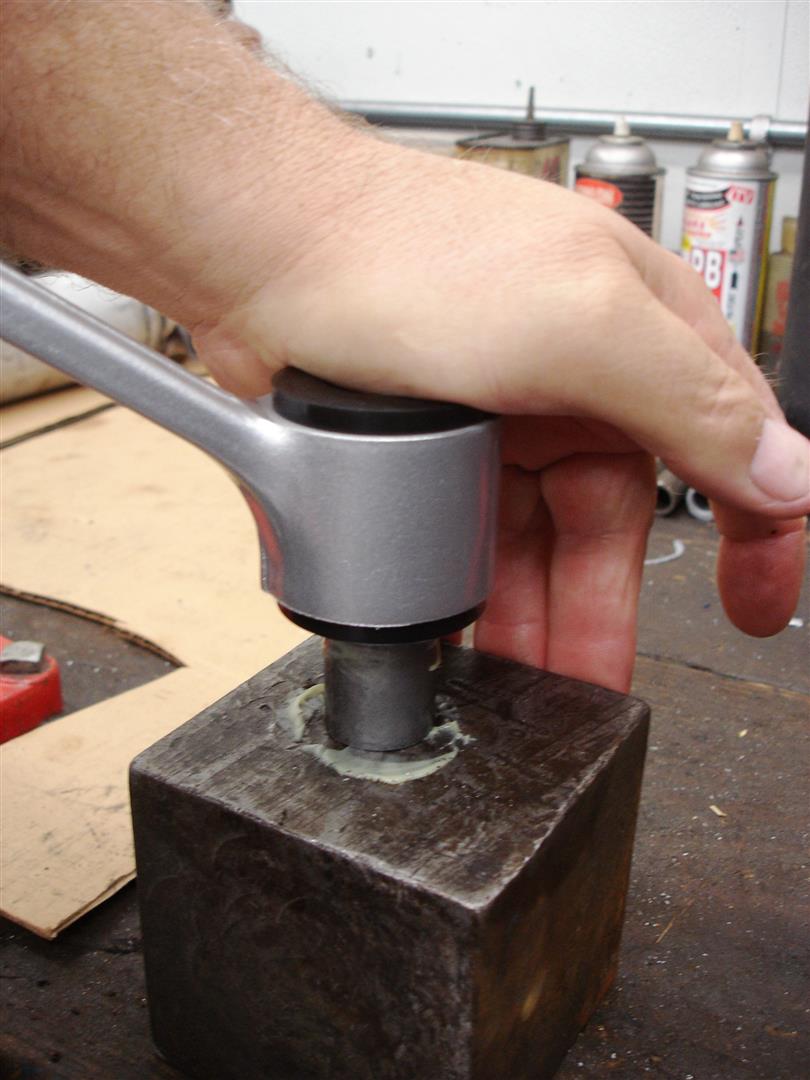
Now the smaller diameter bushing is pushed into the control arm. Sometimes they can be pushed in by hand, although I find these bushings require more effort.
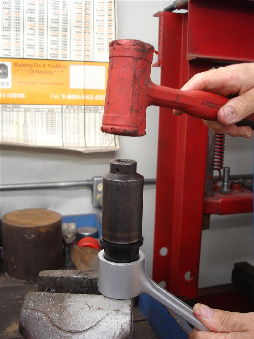
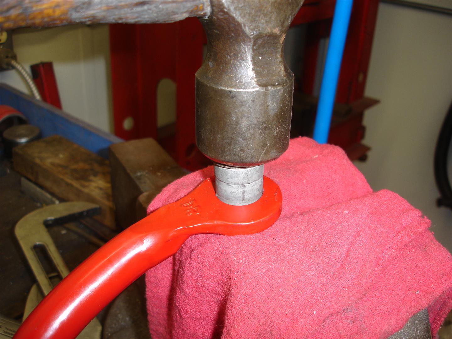
This hammer and socket works well and is required most times to seat the bushing into the control arm. First and foremost, make sure the control arm is supported before any load is applied during the bushing install. Note the plastic hammer. It should not require a tremendous amount of effort to push the bushing in place. Make sure your socket or installer does not contact the control arm shafts aluminum threads as it installs the bushing.
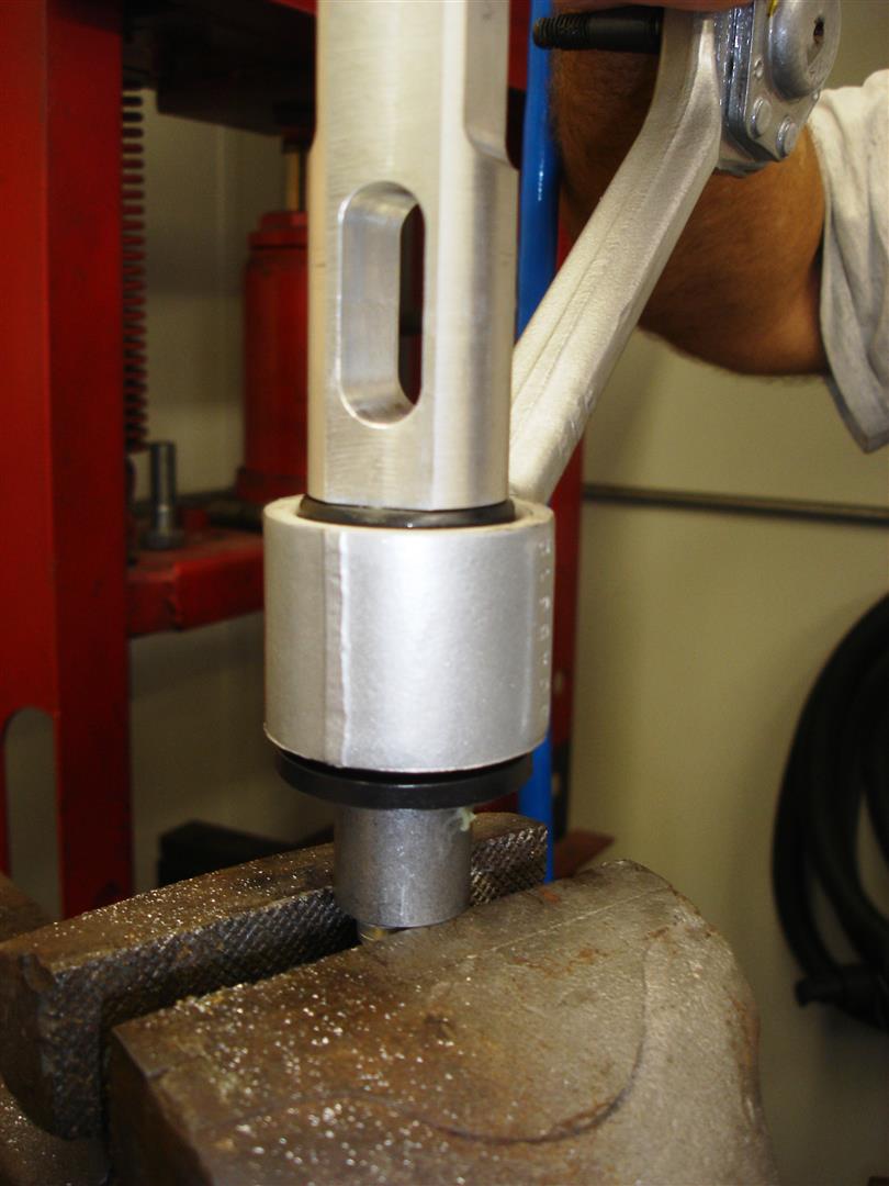
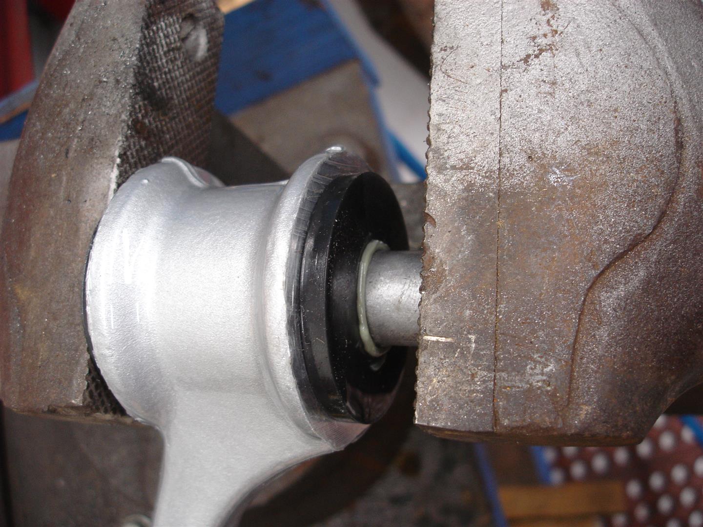
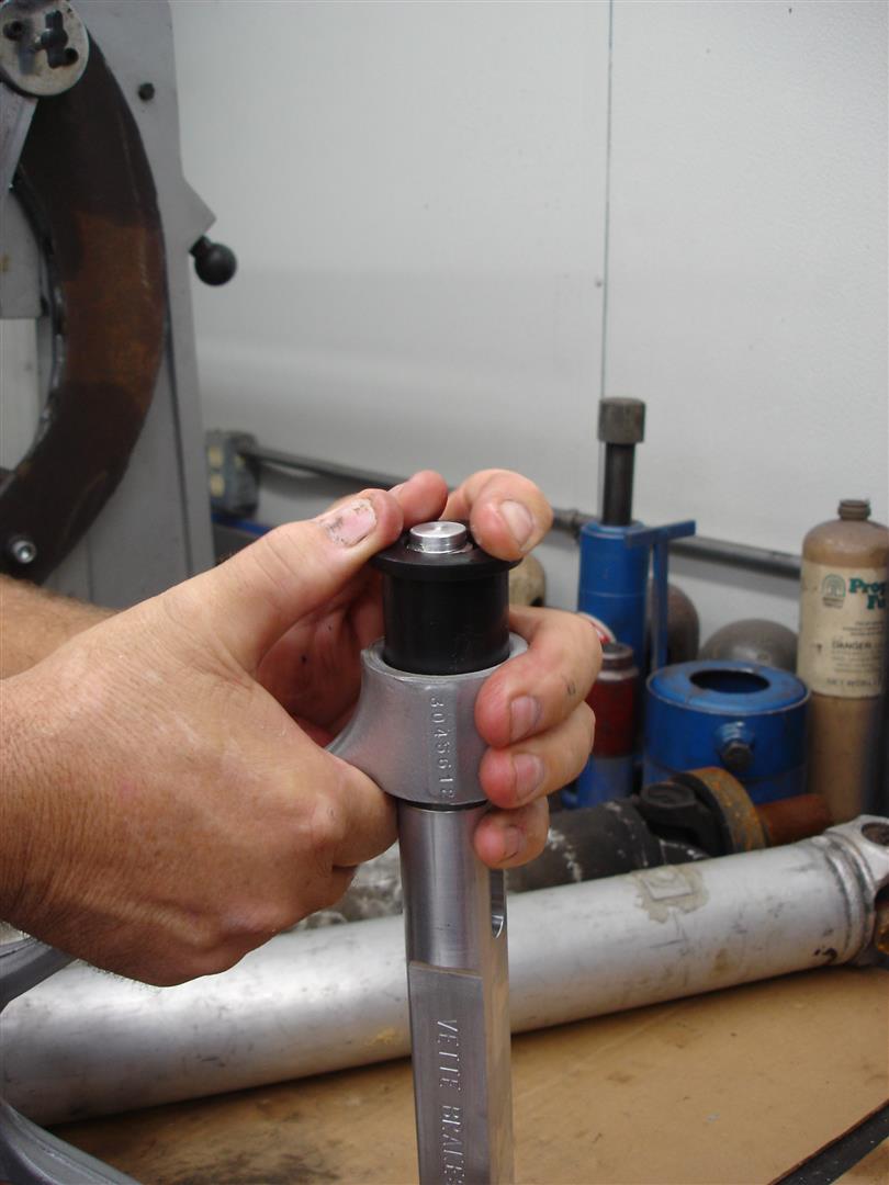
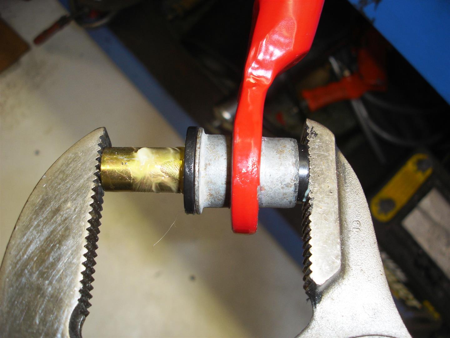
Here the sleeve is being installed into the bushing. The arm is pushed downward by hand pressure only to seat the sleeve. Apply plenty of silicone grease to the sleeve before installation. The control arms shaft threads come very close to the vise jaws during this procedure. Care must be taken to avoid damage.
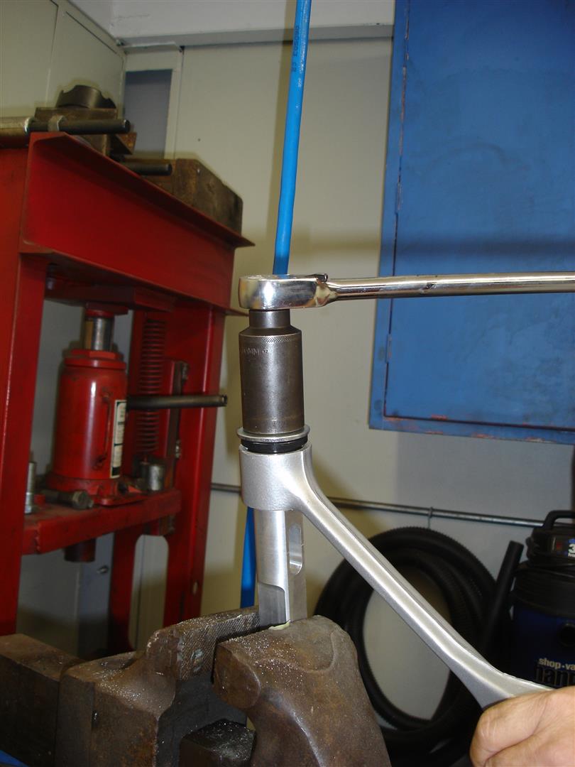
Now the part where good judgment comes in to play. GM does not have a recommended torque setting for the upper control arm shaft nuts. The upper control arms were not to be serviced; hence they have no guidelines to go by. It is very hard to determine what the initial torque was because a locking compound was used on the threads. In the shop, we apply blue Loc-tite to both shaft end nuts and torque them to 35-40 foot pounds. This may not seem very tight but we are dealing with aluminum threads. Once the project is complete and has been driven a couple hundred miles we recommended that the torque be checked. So far we have not had any problems with this torque setting. Keep this in mind, unlike the rubber bushings that would keep the control arm from disassembling if the nuts backed off the urethane bushings will come out. What happens next is total loss of control of the spindle knuckle.
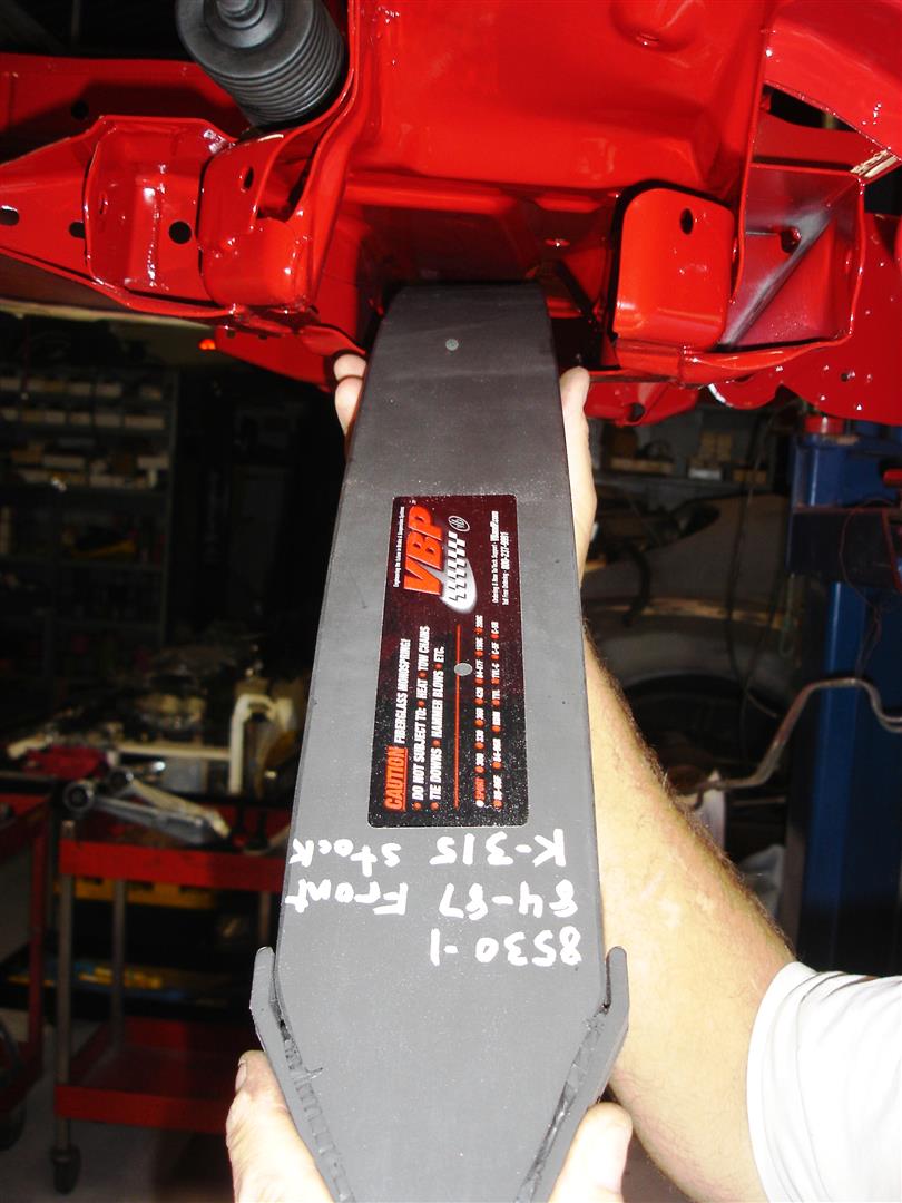
Front spring installation is next. Here we are installing a stock spring rate in this 1985 Corvette for a smooth, all road surfaces ride. Many opt for a stiff front spring in the belief the tire/wheel assembly will be pushed onto the road surface, whereas the softer spring will let the tire leave the road surface easier. This is true to some degree if the frame supporting the front suspension is stiff. If not, the stiff spring bounces the tire over the road surface. I’ll discuss the spring rate further as we proceed. Always check the inner bottom side of the crossmember for any raised metal that might gouge the spring once it is in place. The spring is put in place and pivots loosely installed until the control arms are in place.
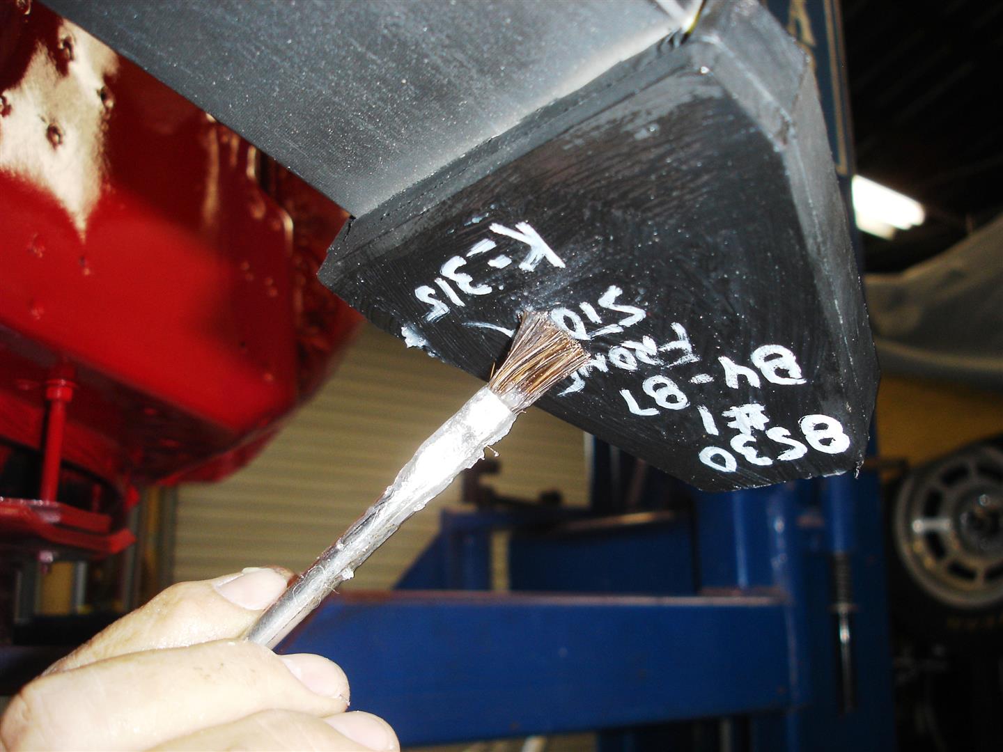
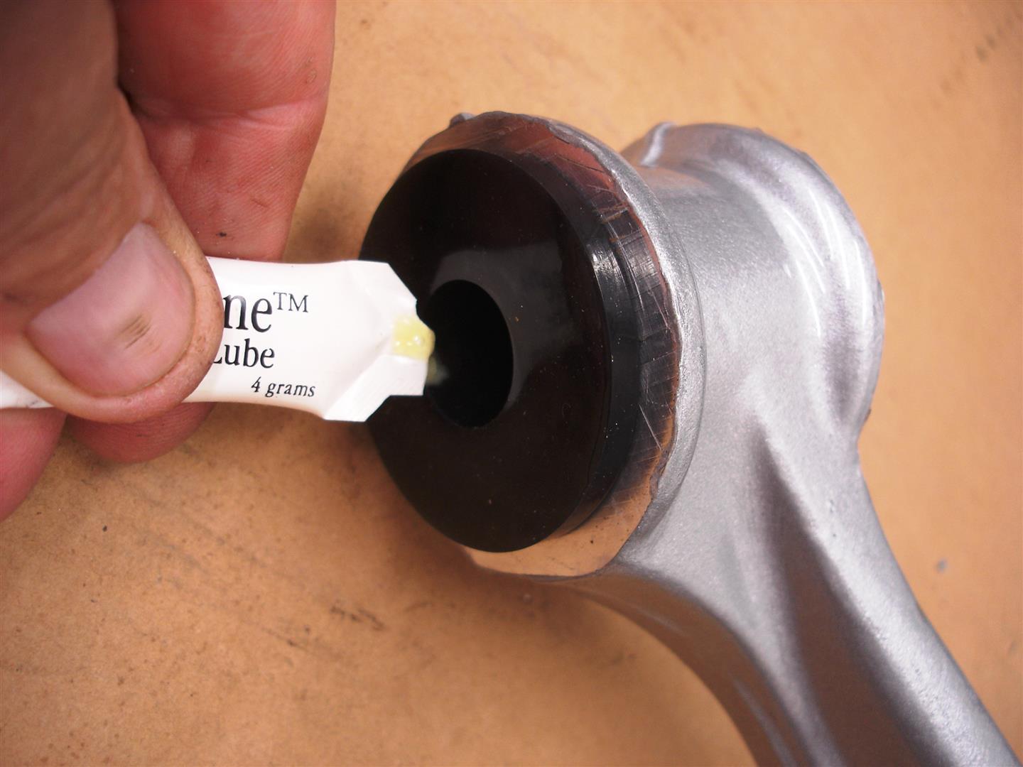
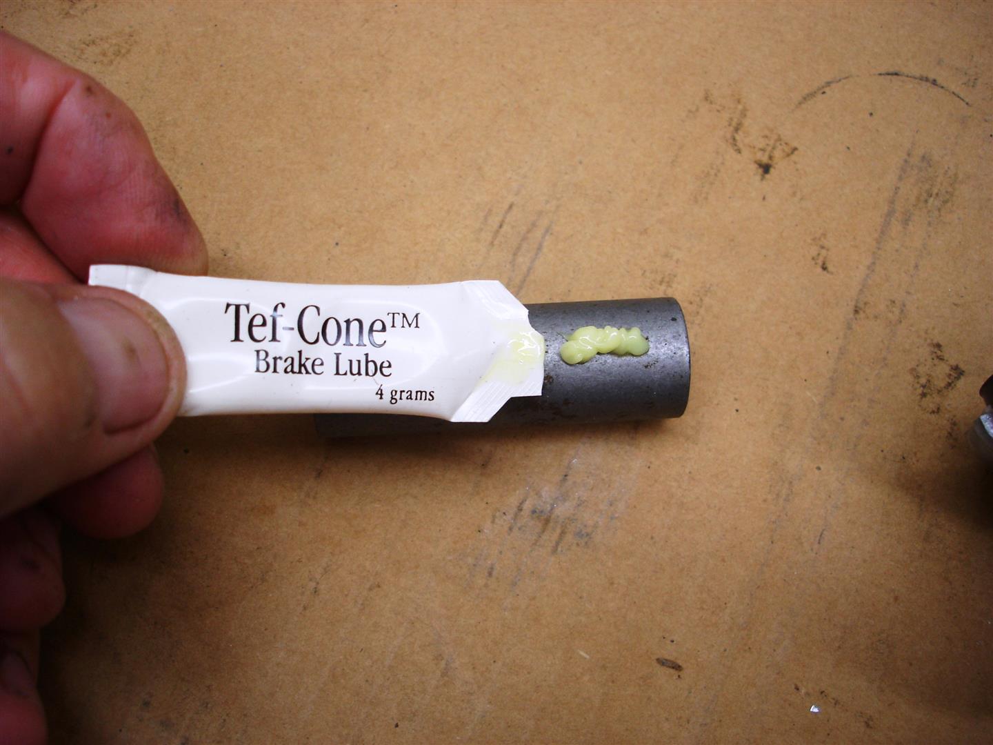
I apply a liberal amount of silicone grease to the urethane end cushions of the front spring for smooth spring action. These urethane spring pads are replaceable and may require replacement after 5-6 years depending on your road conditions. GM used rubber pads that tend to last longer but you lose road feel on track set-up Corvettes. The spring pivot mount retainers should be torqued to 48 ft lbs. I wait until the spring is in place with the spindle knuckles connected to both the upper and lower control arms before torqueing. This flattens out the spring and assures the spring is centered in the mounts.
The lower control arms are installed with more of that silicone grease on the outer bushing surfaces. It is critical that the bushings fit tight in the pivot to prevent suspension geometry changes. That means that the inner sleeve should be level or slightly below the outer surface of the urethane bushing.

The tight fitting lower control arm bushings require some help with this plastic dead-blow hammer during installation. Try to keep the control arm ends going in even avoiding a binding condition.
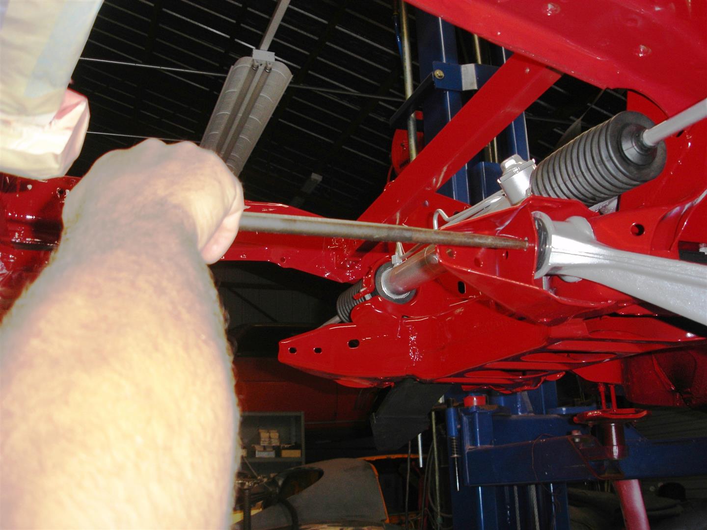
Once the sleeves are close a line-up bar is used to center the sleeves for bolt installation. It works best if both sleeves are centered before attempting bolt installation.
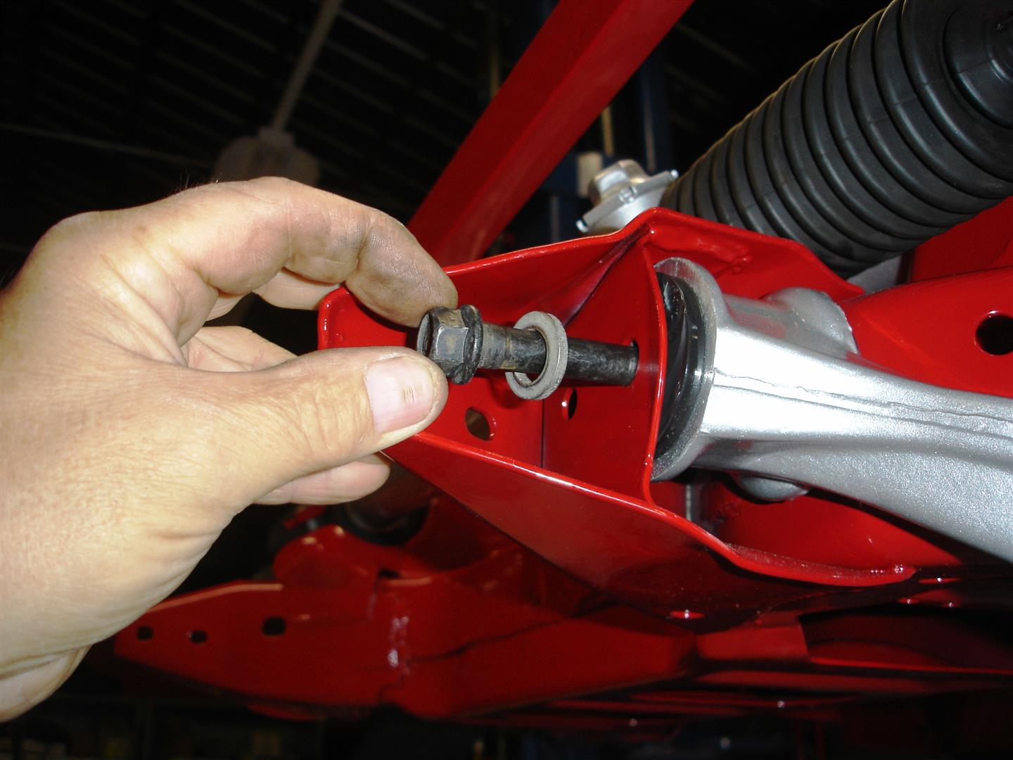
The hardened original GM bolts are installed with an extra thick washer at the bolt and nut sides. Because we are using urethane bushings, the bolts can be tightened and torqued now. The spring makes access to the nuts somewhat aggravating but not impossible. It is always recommended that the torque wrench be applied to the nut if at all possible. This assures an accurate torque reading whereas the bolt as some inherent twist and the applied torque will not be as great. The lower control arm nuts should be torqued to 82ft lbs. If the bushings are set-up correctly, the lower arms should move with some tension, not in a rigid state. If they just fall down on their own weight, the sleeves are too long and the bushings will move around and cause geometry changes. If the only way to move the control arm is with a jack the bushings are too tight and smooth suspension travel will not occur which is what we want.

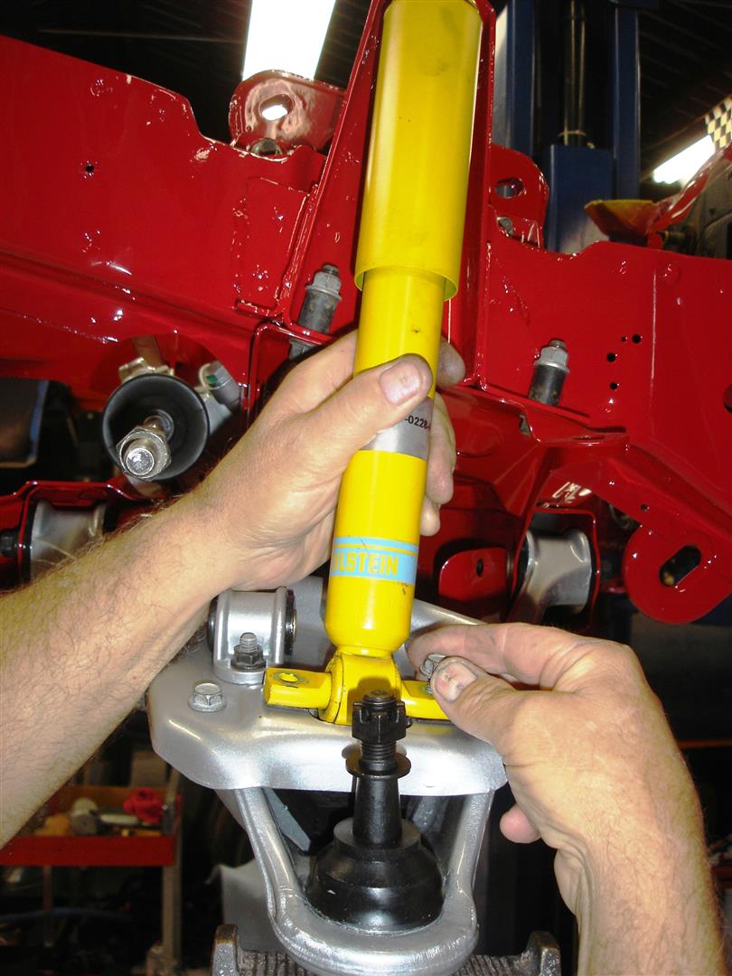
This early 1984-1987 lower control arm has had the shock absorber/sway bar plate installed after the control arm is in place. Later 1988-1996 lower control arms do not use this plate and have the sway bar and shock absorbers mounted directly to the control arm. The later control arms are a better choice for a serious Road Race or Autocross competitor. The shock/sway bar mount plate requires constant checking for tightness when the 84-87 Corvette is used on track days. The tall jack stand is placed under the lower ball joint to prepare the control arms for spindle knuckle installation. May seem obvious but the grease fitting should be left out or taken out during this procedure to avoid breaking it off in the ball joint.
The shocks are installed using the original GM metric bolts into the J-clips. The J-clips make the install easy but they are a weak link to some degree. They do not have the same holding power as a nut. The bolts should be torqued to 19ft lbs. Later 1988-1996 have through bolts and nuts holding the shocks the nuts should be torqued to 20ft lbs. The sway bar link mount to plate bolts and nuts are torqued to 22ft lbs.
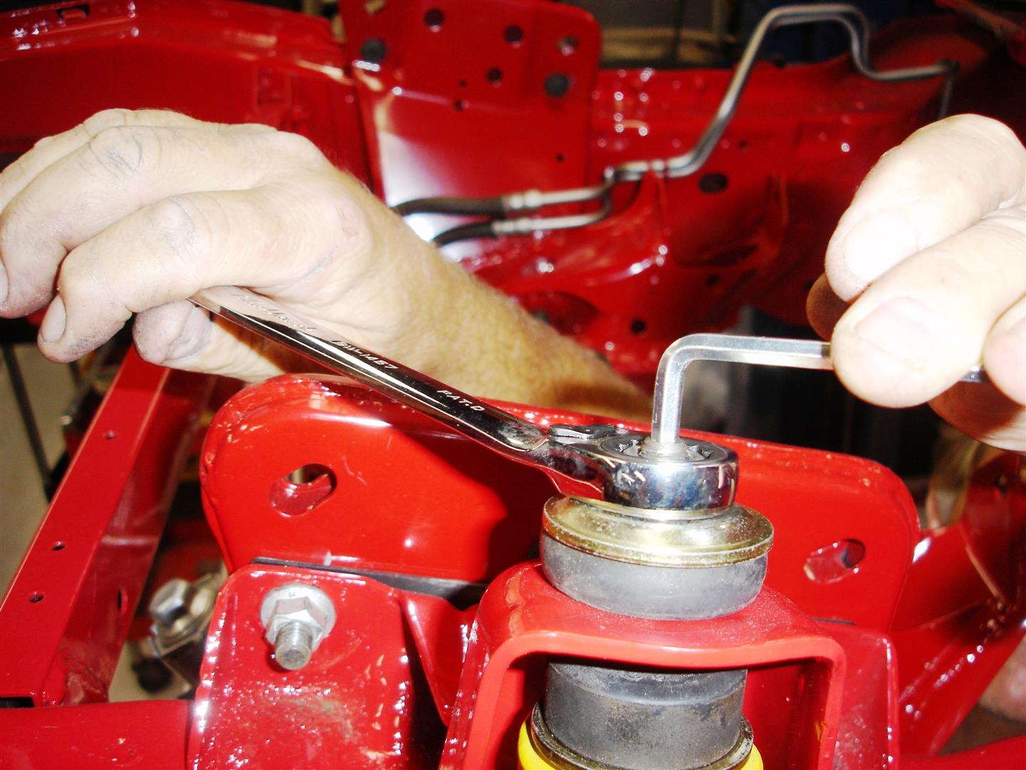
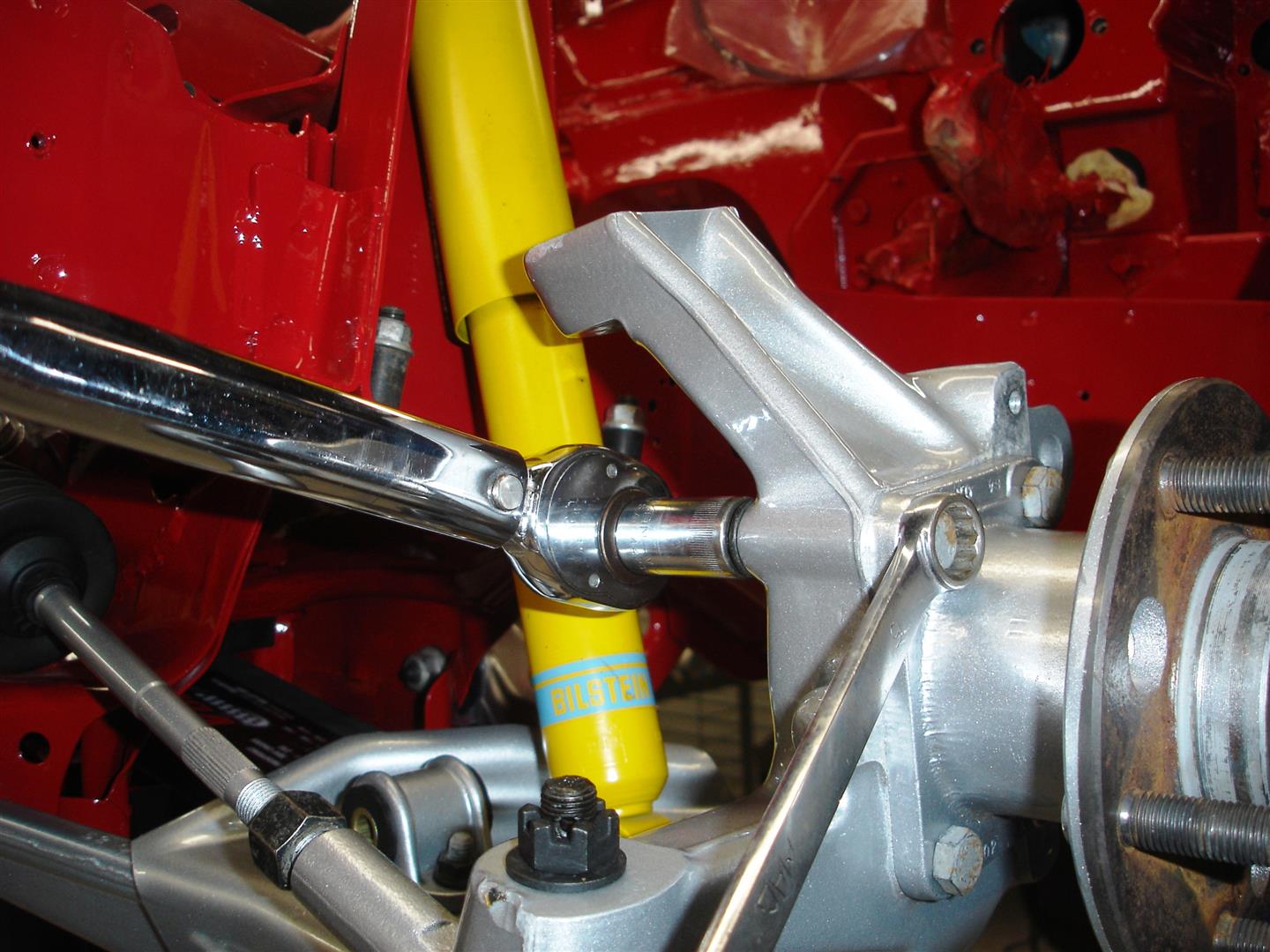
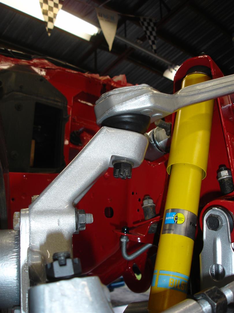
Once the upper shock mount is in place, the jack holding up the lower control arm can be released. I usually do the assembly this way to give me plenty of access to the components without a jack in the way. These Bilstein shock upper studs make it simple to correctly tighten the upper mount. They have a shoulder on the stud that the upper washer should be seated on; this prevents over tightening and cushion damage. The locking nut that Bilstein provides with the shock requires the use of an Allen wrench to prevent spinning the shocks shaft. A turn or maybe two most likely will not cause an issue. Spinning the shaft can cause the shaft to come out of the piston. Once the washer is seated, the nut should be torqued to 19ft lbs. In most cases, the cushions have enough drag once the washer is seated to allow the use of a torque wrench for the final check. Some aftermarket shocks do not have a shoulder for the washer to seat against. Run the nut down until the cushions begin to bulge. If not, the cushions will be crushed and split over time.
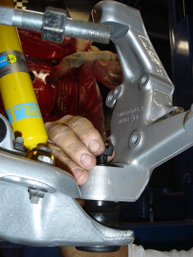
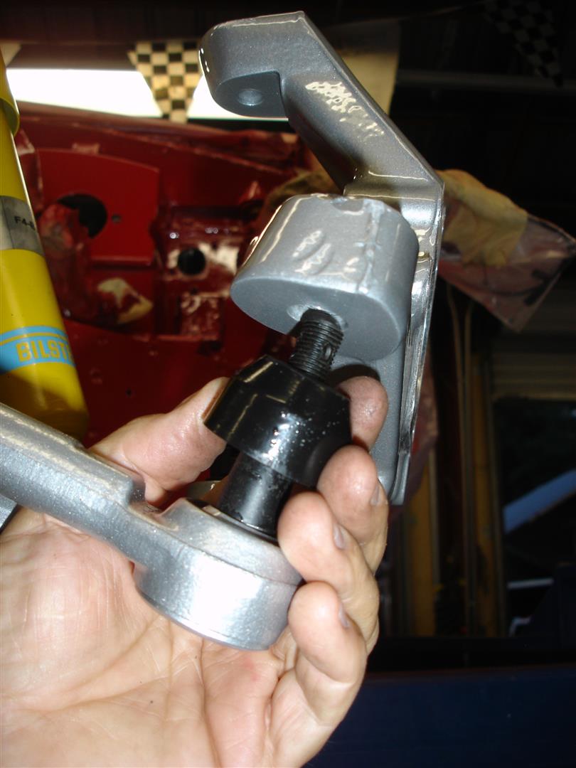
Now the spindle knuckle is set onto the lower ball joint stud. Note the washer between the nut and spindle knuckle: it must not be left out. The washer prevents aluminum damage as the nut is torqued. The ball joint stud is torqued to 50ft lbs, then the nut turned to the first available opening in the castellated nut and ball joint stud hole. Never back off the nut to align the cotter pin hole. A note of caution: if any paint or refinishing material is in the spindle knuckles ball joint stud hole, it must be removed or an improper torque reading will result. As the debris breaks away, the stud becomes loose. Eventually the loose stud will ruin the spindle knuckle as it wobbles around.
I replaced the original rubber tie-rod end boots with these Corvette Central urethane replacements. Although they are not retained to the tie-rod end as the originals, they will last much longer and cannot be blown out from over-greasing. All too often we find the inner wheel drum full of blobs of grease and dirt from blown out ball joint and tie-rod end boots. If greased properly (2-3 pumps of grease), the seals will not blow out or have major blobs of grease oozing out of the joints. If the urethane joints or ends are over-greased, wipe all the excess grease off and you will prevent dirty inner wheel drums. Another fact the entire front end should be greased 3 times for proper grease penetration. One time while the steering wheel is centered, again when rotated fully left, and finally when rotated fully right. It does not matter how you go right to left or vice versa; the rotation assures even greasing. The old adage applies here, a picture paints a thousand words and those grease/dirt blobs not only look bad they affect wheel balance. Although not a major concern, over a long period of time cumulatively it can alter wheel balance.
Two procedures here: the tie-rod end nut (with the washer under it) should be torqued to 32ft lbs and then tightened to line-up the cotter pin hole. The wheel bearing assembly is installed and (the nuts) torqued to 46ft lbs. If any coatings were applied, make sure the bearing and spindle knuckle seat areas are clean and free of any coatings. As the bearing works on the coatings between the mating surfaces, they break apart and the torque you think you have is much less.
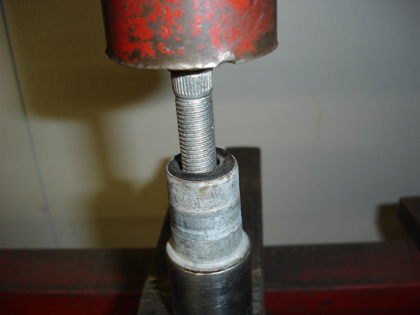
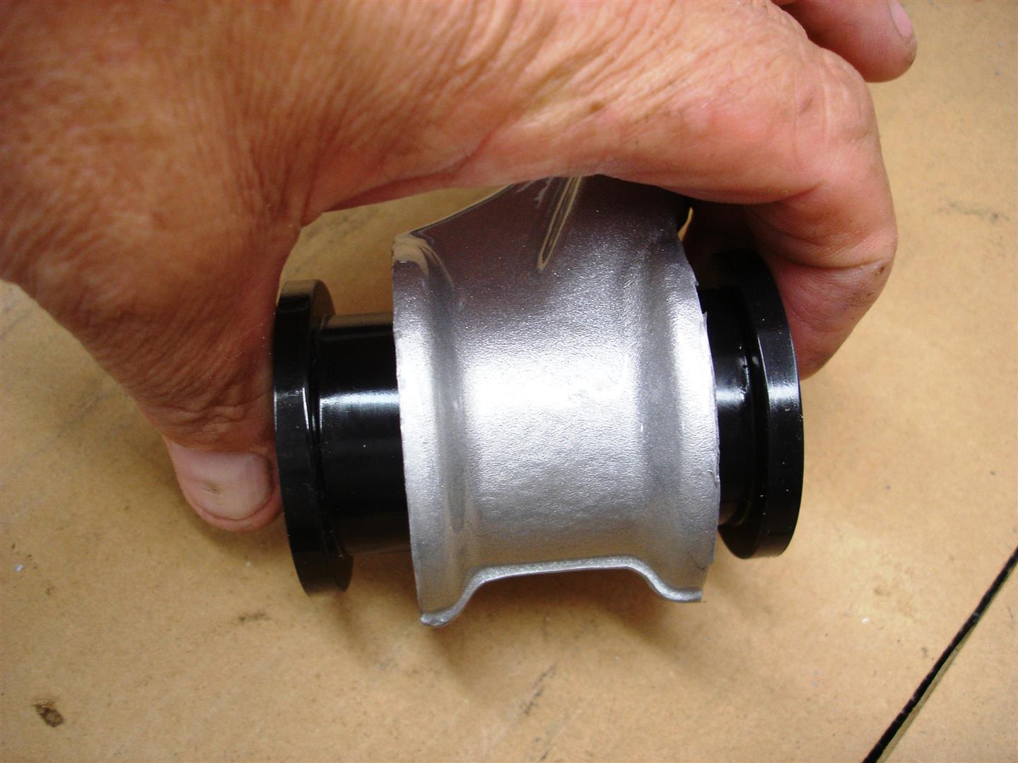
I go back to the bench and prep the sway bar bushing outer sleeves for the new urethane bushings. The sway bar end bushings come from the factory as one assembly; they are easily tapped out of the ends. The sleeve must be pushed out of the rubber, a socket is used as the receiver and a wheel stud pushes out the sleeve. I have access to a press, a bench vise will also work for this procedure, just takes more effort. Make sure the pusher tool you use is smaller diameter than the original sleeve or it will be caught in the rubber.
Once the inner sleeve is out, the rubber is torn away from the outer sleeve and forced out. Remember we need this outer sleeve so take care to avoid distorting it. After the rubber is removed any traces of the rubber need to be removed with a knife, scraper or coarse sandpaper so the bushing fits without binding during installation.
The clean outer sleeve is tapped into the sway bar end until it seats on the sleeve’s shoulder.
The urethane rubber bushing from the Corvette Central sway bar end link kit is easily pushed in by hand into the outer sleeve. The inner sleeve is lubricated and pushed into the urethane bushing. This large pair of Channel-lock pliers should do the job without too much effort. If a large hammer is required for the inner sleeve install, chances are the outer sleeve has some old rubber left behind and the sway link will be too tight.

Your urethane bushing kit will come with this auxiliary urethane sleeve that fits over the existing outer sleeve. The auxiliary outer bushing prevents the inner bushing from coming out of the end link during loading. The belt sander is used to make the outer bushing level with the inner steel sleeve. If the auxiliary bushing is not machined, it will bind the assembly in the end link and eventually tear the auxiliary bushing and the assembly will become loose.
One of the first questions when ordering a urethane bushing set will be the sway bars diameter; GM used a few different diameter sway bars depending on the suspension package. A pair of snap ring pliers (such as these shown) helps a bunch when trying to force a urethane bushing over the sway bar. Silicone grease is applied before the bushing is installed and after to make sure the well worked sway bar is lubricated. Due to the open location of the sway bar pivot bushings, they often end up with plenty of dirt and debris mixed with the grease that finds its way between the bar and the urethane bushings. This is often the place that the urethane squeak begins. To avoid the squeaks while preventing sway bar and bushing damage, an annual disassembly and cleaning is recommend for those who use their Corvette on a daily basis. I have seen the steel bars worn with deep gouges from road dirt and grease as it chews into them. Of course the urethane bushings also wear and become loose overtime.

Once the bushings are installed with plenty of lube is on the bar and bushing, the assembly is put in place on the frame rail. The best policy is to install all the bolts and turn them in about half way. This makes installing the end links easier. Once the end links are installed, the pivot mounting bolts are torqued to 40ft lbs. It is very important that the sway bar pivot mounting bolts hold the 40ft lbs of torque. If the bolts or bolt hole treads are questionable and the bolts pull out, the sway bar cannot do its job. I often have to install a 10mm x 1.50 heli-coil into the frame bolt threads to assure a tight bolt. Heli-coil kits are available from most auto parts supplier and major hardware chains.

Now the end links are installed placing both links driver and passenger side onto the lower bushing with the other end on the sway bar. I find it easier to install the lower bolts on both sides first, placing them with the bolt head towards the rear of the car. If the bolts are turned around they can dig into the shock tube. I then install the upper bolts through the sway bar bushings. After all the bolts are installed, I snug them up and torque them to 35ft lbs.
This is another C4 that had upper control arm work that represents a factory control arm shaft. The upper control arm shafts use the concave thick washers to center and retain the shafts. Make sure the concave side goes towards the control arm shaft, there will be two of these concave washers, one on each side of the shaft. The lock nut goes on after the concave washer. Once the alignment is completed, the nuts should be torqued to 37ft lbs. I always check the torque of these bolts after a Corvette returns from the alignment shop.
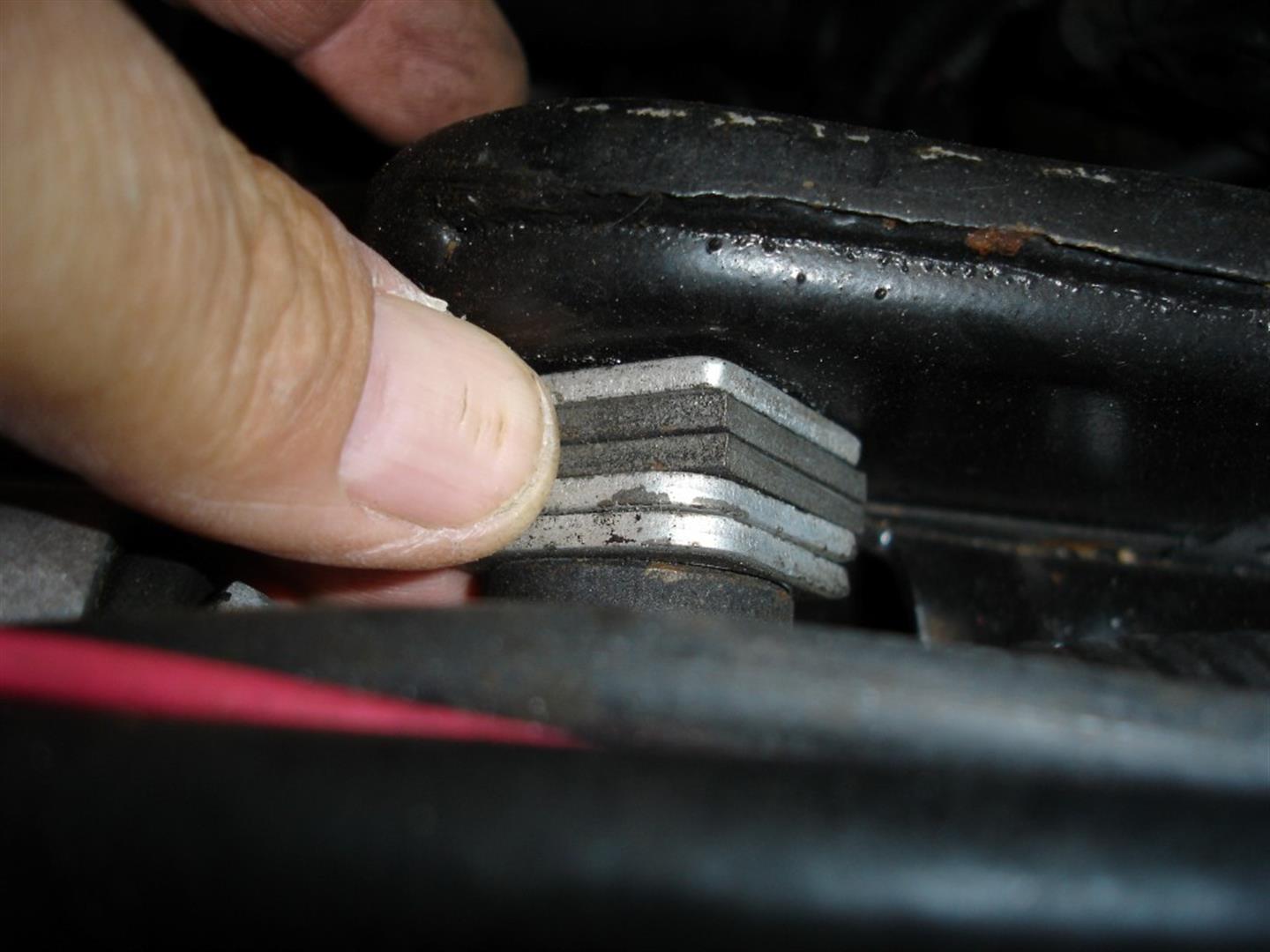
The shim pack goes between the frame riser and a spacer. As mentioned above, a concave washer goes against both sides the control arm shaft. A spacer is also placed against the concave washer on the inside to preset caster and camber. 1984-1985 Corvettes have a thin spacer at the front control arm shaft retaining bolt and a thicker spacer at the rear bolt. This was for the maximum 3 degrees of positive caster that GM suggested in their Alignment Specs. By 1986, GM revised the positive caster to 6 degrees for better high speed stability. This was long before any suspension component upgrades took place in 1988. In the shop, I swap the thick spacer to the front, placing the thin at the rear to achieve at least 6 degrees of positive caster for the best possible handling. If you look at any original 1986-1996 Corvette upper control arm, you will find the washers are thick at front thin at the rear. Another note: if you look at the factory service manual, they show placing the thin spacer up front until the 1989. This is because the manuals are not completely rewritten until a new generation is on the scene. The alignment shop will install the correct amount of shims to set alignment. It is always best to record where the shims were during disassembly and then put them back like they were for the trip to the alignment shop.
I use a deep 18mm socket to access the upper control arm shaft nuts during assembly. When the front wheels are unloaded, the control arm drops down, making the nut much easier to access. The swivel shown should not be used during the torqueing process.
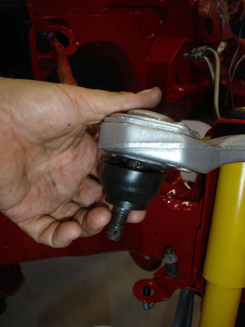
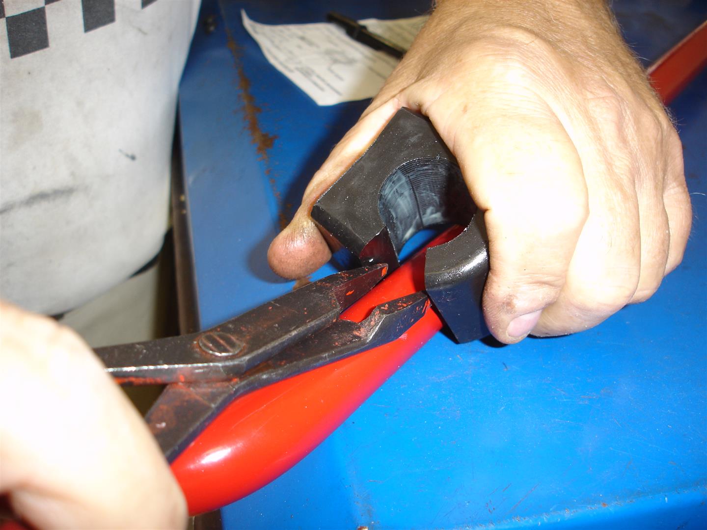
You may have noticed that the upper ball joints were not replaced. Upper ball joints do not wear at the same rate as the lower ball joints. The lower ball joints handle the vehicle weight while the upper joints are for stability. After the control arms are installed, Corvette Central supplied urethane ball joint boots replace the original rubber boots. I use a razor knife, cutting the boot as close as possible to the old boots metal retainer.
Washers placed under the ball joint stud nut are a necessity to avoid aluminum damage from the nut as it is tightened. It is also a good practice to tighten per the GM service manual, torqueing to their spec of 33ft lbs, then turn the nut until the cotter pin hole lines up. Always go tighter to line up the hole. Never loosen. Now the entire suspension gets a once over for cotter pins and correct fastener torque.
On the next installment, we tackle the rear suspension bushing installation and component installation.
This is the second installment of a C4 suspension overview series. Click to view the first article, Click to view the third article.
Story and photos courtesy Chris Petris
I have a 1984 Corvette here in Australia and have rebuilt the front and rear suspension using the tips in your articles. I have an issue with the front and rear suspension travel, or lack of it. Now I am in the middle of a very big Resto on it and I did the brakes and suspension 3 years ago now. I suspect that the urethane grease used for lube has dried and now the rubbers maybe binding. I have sprayed the front upper control arms and one has started to free up. I have used silicone spray. Is there anything else you think I should look for as the front is sitting way too high, I estimate 4”.
“Now the smaller diameter bushing is pushed into the control arm. Sometimes they can be pushed in by hand, although I find these bushings require more effort.” I cannot seem to get the smaller diameter bushing pushed into the control arm… Do you have any tips: tools to use?
I also have another question about the front spring replacement. I just received a replacement front spring for my ’95 vette and it appears I need to reuse the bottom half of my existing spring bushing, but they seem like they are one piece, not a top and bottom half. Do you simply cut them in half and scrape it off of the existing spring as best as possble? Once off should an appoxy be used to affix it to the new spring?
Thank you!